Recently I have begun what might be the start of a nostalgic journey in vacuum tubes. I credit this addiction to Paul of Mr. Carlson’s Lab (You should check out his YouTube channel in case you don’t know him – https://www.youtube.com/watch?v=qqmegXoB7lA – extremely knowledgeable guy with an amazing skill to explain stuff)
The EICO 950B, the resistance capacitance bridge and the capacitor leak tester – I do have other tiny things that can measure capacitance, but nothing compares to this one, or the Heathkit or a high voltage DC capacitor leak tester.
The reason why I got this EICO 950B in the first place is another massive project – the biggest one I’ve undertaken so far – a 1950s TEK 549 (Yes, I am not crazy and I plan to bring an orphaned 549 back to life). It’s been on for a month now, and I’ve spent about 100+ hours on it as of today (weekends, late evenings, day after day). It is a vacuum tube scope and I need a leak tester to check the caps in it. (Watch out for my post on that once I’m done with it)
But I digress. I was looking for a decent heathkit or the EICO 950 to help me restore it when I stumbled upon this little treasure. Sometimes, in the process of looking for something, you come across a few folks, who possessed a wide spectrum of skills and abilities. I don’t want to call it “buying” as I deem it an honor to possess these items left behind by a great soul. I saw a bunch of equipment on sale and when I saw the EICO I asked for a picture of it. I was blown away by how well kept it was, and went there to pick it up and was amazed to see the amount of electronic instruments he had – collections all the way from 1950. It ranged from a tiny 12V DC power supply all the way to RF gear. I became curious to know more about him. His family were great – his daughter and her husband were nice, sweet and patient, they showed me all his toys –
Robert Merville Gale –

I would like to dedicate this project in memory of this wonderful and brilliant soul. Having restored and repaired a great many things in the past, that have been owned and used by others, but I’ve never encountered how beautiful and well maintained this was.
I digress again. So let’s see how I got it back to life.
Important: These instruments contain deadly voltages and exposed leads/components. If you are not familiar with High Voltage circuits, DO NOT attempt to repair/restore or even open this. Even if you are familiar with solid state electronics, do not try this unless you really understand the risks involved with working on Vacuum Tubes and High Voltage DC and know the safety procedures to follow.
It can kill you. Ensure you are skilled enough to do this.
This is how pristine it looked when I picked it up.


But obviously, that’s just the external looks, there are leaky caps on this inside which are waiting to blow up if I ever power it up. So the first thing I did was to CUT THE POWER CORD (to ensure I’m not tempted to ever power it up, that is).
And here you go, this is what it looked like on the inside. The wax/paper caps were all dead, leaking, and waiting to short-circuit if I ever powered it up.
The Magic eye Tube 1629 and Rectifier, the all famous 6X5


The basic circuit of this unit is very simple. It’s an AC bridge, with a differential voltage that is pointing to the grid of the magic eye. In the leak test mode, it’s a simple RC charging circuit with a monitor resistor to reflect the charging current to the grid – this ensures that the eye opens if there is no current, and is closed (fully lit) if there is a constant charging current or a LEAK.
NOTE: DO NOT CONNECT MULTIMETER or any other device IN PARALLEL TO CAPACITOR TO MEASURE VOLTAGE WHILE LEAK TESTING. The current drain by the meter can cause the eye to close (especially paper/mica mode)
ALSO AFTER TESTING, the first step is to rotate VOLTAGE DIAL TO 0, THEN REMOVE CAP. OR ELSE THE CAP WILL BE CHARGED and can surprise you with a nasty shock.
The next step was to do a complete physical inspection, look for broken parts, shorts, missing cables, broken connectors and so on. As expected, I found broken cables, joints, exposed cabling.
Now I needed to formulate a course of action, and this was my plan –
- Clean and inspect (Both inside and the outside)
- Make the solder joints, connections a bit more organized (I might have OCD)
- Verify the schematics – This is not factory made, the person who assembled it may have made mistakes.
- Use heat shrink tubing to cover all exposed joints
- Fix broken joints connections
- Replace all CAPS, no question of reusing ANY
- Check all resistors – replace if required
- Check transformer for short
- Check Tubes – Physical, and Tester
- Power up heater for tubes, ONLY heater and confirm they are good
- Using variance slowly power up to 40V (instead of 120V) and measure all voltages, confirm the voltages at various points to confirm all components are working fine
- Fix issues if any, then slowly ramp up to 120V.
- Test the caps
- Thank Sir Robert Merville Gale for his knowledge and love for all his toys, and for maintaining them so well over all these years.
Here is what all I found,
Some broken joints.

A little dangerous wiring/assembly. Lots of exposed conductors, though I wouldn’t blame anyone as it was common those days to have a 500V line exposed inside the chassis.


So I started fixing it. You can see the pictures and how I’ve worked on it, in stages. I do heat shrink all joints/connections, even to Tube sockets.


I have put in a new power cord, a new y-capacitor and replaced all the electrolytic ones. Have used two in series to keep the capacitance close to the original and the rectifier tube specs call for a maximum filter cap of 4uF. As the tube heats up slowly, it should not cause any trouble even if I have a high value cap, but I wanted to play it safe and keep the surge current as low as possible to protect the rectifier tube. But remember, a very high value cap can load and burn the rectifier tube.
Based on a comment from Michael, I’m adding a bit of explanation here – The 8μF 525V capacitor can be made up using two 16μF or 22μF /350V or 450V in series. Add parallel resistors of 470KΩ/1W across each cap to keep the voltage loading on both capacitors approximately the same. Do not go too high on the resistor as it should have a larger current than the leakage of the caps. Too low value of resistors will load the circuit up. Ensure you have a at least 1mA leakage current through the resistor network.

If you are not adding the resistors, remember the rules for series capacitors. Do add 40% tolerance from its rated voltage. ie, do not replace 2X100V caps for against a 200V Capacitor, as voltages may not be exactly divided across capacitors due to tolerance in capacitance as well as leakage current/resistance.
Another strange value to find today is C8 – 0.25uF/600V. Use any modern film cap, with value of 0.22uF/600V or 1000V. If not available, use 0.33uF/600V or 1000V. You can pick the capacitor with higher voltage value like 1600V if they are available.
The Y cap was taken from an old SMPS – (C7 in the original schematic). The power cord was changed to 3rd pin and grounded earth to chassis.


I disconnected the HV outputs from transformer secondary to keep plates/rectifier from being energized, as well as to not power the filter caps.
After verifying the schematics, the first test was the tube test, with just the heater power. I checked the transformer as well in this process and saw the heater glow from both the tube and the magic eye.

Now, the AC Bridge needed 3 Precision Caps and 4 Precision resistors. Unfortunately I didn’t have the caps to replace it right away, so decided to do the precision caps later as my immediate need was for leak testing, and placed the order for precision caps.
Note: You need not order the exact value as per original spec, as it is rare. You just need to keep the ration (capacitance ratio) the same. You could google it to find more details. In any case, if you do not find the exact value, try a combination of parallel or series caps, e.g. If you need 2uF 1%, get 2 x 1uF 1%. I am ordering 22000pF, 220pF, 2.2uF, 1%. The resistors are good, so I’m not replacing them.
I rechecked the schematic, connections, wiring, and now on to variac on, connected HV secondary to circuit, Slowly raising input voltage via variac to see as the tubes heat up, and watching for magic eye to glow.
You can see the first light up, after so many years, still on 60V power. I used one of its own old caps, to check for a leak and you can see the result for a 400V cap with 88v input 🙂


So it all looks good. While I wait for my precision caps to arrive, I can finish rest of the tasks, replace the last few 0.01uf caps, the main 0.25 (I did 2X0.1uf) and do a final clean up.


And Finally, I am all set :). I am ready to head back to my TEK Project. I will replace the Precision caps once they arrive, but as of now it’s not too urgent as I’m not using this instrument to measure capacitance, but just to test the leak function.


Here is the final picture, all set and ready to help me with my mega TEK project.
Remember : It is not just the caps which needs attention. Always check the resistors too. They can drift and cause errors in leakge measurement or even bridge measurements.
For those of you wanting to attempt something similar, here is the component list –
C1/C9 – Power Supply Filter. Don’t go too high with replacement values as it can load the 6X5 rectifier Tube.
C2-C4 – Precision Caps – used for doing capacitance measurement – get 1% tolerance replacement/ No need for exact value, use exact ratio of values.
C5-C6 -> Coupling
C7 -> Y Cap.
C8 – Not sure, looks like it’s used to reduce the Pot Noise
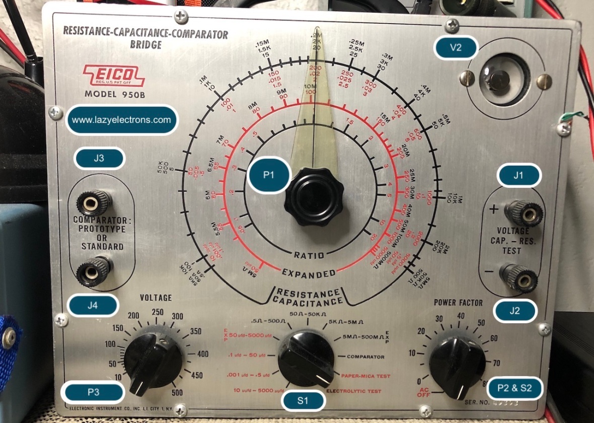
Pot 1 -P1 – Main Dial – Cap/Resistance Value
Pot 2 – P2 – Power Factor Pot/ On-Off Switch
Pot3 – P3 – Voltage control for Leak Testing
Resistors -> No need of replacement in most cases, still check all values.
WARNING:
If you are using this instrument to test high value electrolytic, eg. 150uf 450V, or similar ones you find in SMPS, ensure you discharge it gracefully after testing, ie, slowly rotate the voltage dial back to zero, else, the Capacitor can burn the voltage control POT by quick discharge, as a charged capacitor can deliver strong current at high voltages on values above 25uF.Or in short there is no discharge resistor in this design.
Here is a quick overview of the schematic.

There are three secondary Windings.
1. for Heater, 12.6v and 6.3v for Magic eye and 6X5 respectively.
2. Second winding is ~ 54V ac, used for the bridge for capacitance/resistance measurement.
3. Third one, this is the High voltage one, which is rectified via 6X5 and doubled/filtered using C1 and C9.
Rest of the circuitry is mostly switches to control the function – ie Leak or R/C Measurement. For Leak testing pot P3 controls the output voltage.
J1/J2 is the test terminal.
J3/J4 is for connecting a known value/reference cap/resistor for comparison.
Important note: In chassis testing of caps
If you check the leakage test schematic, you will notice that the tester sends a -ve test voltage to the capacitor. Or in other words, +ve terminal of the capacitor is close to ground where as -ve is elevated close to test voltage.
Why bother? well, assume you are testing a capacitor mounted on a chassis. Sometimes we can disconnect the only positive terminal of the capacitor from the circuit for testing, as negative of the capacitor typically goes to ground or chassis. Now you attach the tester to test the cap at 300V, even though the positive terminal is disconnected from the circuit, since the -ve is connected to cap and chassis ground, your equipment chassis is sitting at -300V or close to it. So be careful. Either keep the tester off an isolation transformer or do not touch the chassis during testing.

And a snap from the work in progress schematic.

Back to Home Page for More Crazy Stuff

Hi,
Nice to see a great equipment being put back to use again. As you mentioned the leakage tets function is a really valuable function that is not found in many capacitor testers today. The power factor tester too is also quite handy.
I recently got an EICO 950B from eBay in fairly good condition for like $50 with shipping (the device was for $27).I contacted the seller and he was a TV repairman from Massachusetts. I had a hard time getting those film caps but managed to get them finally. Especially the 400V 0.02MFD, but was lucky to find a capacitor of the same value from a couple of xenon flash circuit I had with me. So, now the capacitance tester seems to be like 98-99% close to accuracy. The only thing now I’ve to get fixed is the 10K voltage pot.
I wish I had come across this valuable article before. I was checking an electrolytic 200V 470uF cap and rand down the voltage pot from 150V to 0 and saw some blue flashes from inside. For a moment I saw it through the eye tube glass. which made me think I blew the eye tube. But was lucky it was just the pot. The only 10K I had was a 1/2 W so used it and it is working fine now. But it does get quite warm if I run for long. I definitely need to get the 5W 10K wire wound pot from eBay.
Overall a great piece of hardware!
LikeLike
congratulations on the 950 and good to hear from you. Do not run down the voltage fast after leak test on a high value cap. Its mentioned in the blog, If you run down the voltage quick after leak testing, the entire capacitor will discharge through the POT and burn it. Thats why many prefer Heathkit IT-11/IT-28.
LikeLike
Yes, I learned it the hard way. I would love to get a Heathkit IT-11/28. But they are too pricey and it’s very hard to get a good one at less than $100. Initially I had set aside like $200 to get the IT-11/28, but the guy from the channel “The Radio Shop” told me an EICO 950B should also be fine. So, until I come across one at a good price I’ll hold. For me the hardest part is getting high voltage wax capacitor replacements(like 1.kv and 1.6kv). Ever since CRTs are out most shops have it stacked somewhere in corner and the guys in the shop usually ask me to go through the section where they keep the old stuffs. They say nobody usually comes for those stuffs anymore.
LikeLike
Just wanted to give a follow up to my previous reply. I restored the Eico completely by restoring all the capacitors and some bad resistors too. The capacitance-resistance part works like 98%. So, I’m good with it. As for the voltage leakage test, the voltage is slightly higher at certain graduations than on the panel. But again, one of my friends told me that it’s probably that the pot might not be as good or the graduation may not be perfectly accurate. If I may ask, could you please let me know if the voltage output produced by your unit lets say is set to 50, 100 & 300 etc show exactly the same voltage on a VTVM/Multimeter? If, there is an error how much is it like?
I’m only a little concerned about the leakage part when testing electrolytics. But so far the Eico does the job pretty well.
LikeLike
There will be variation in the output, as not regulated or controlled output. So it will vary slightly based on the input power and other conditions. Also, a multi meter is also a load for such instruments as the current you are measuring is in uA. So the eye may close even with a multi meter in the cap terminals (specially in paper mode)
LikeLike
Thanks for the reply. This is what I noticed too that the multimeter might load the device. I was more worried like lets say I’ve a 50V electrolytic capacitor and if I turn the knob to 50V but if the actual voltage being produced is above 50V then it can be an issue. Especially the modern day caps aren’t very tolerant like vintage ones. IF its 50V then we better stick with 49.99V xD!
LikeLike
Totally agree, Typical calibration procedure for these contains a step to adjust the knob so that the output voltage is close the dial reading. Its more a mechanical adjustment 🙂
LikeLiked by 1 person
I sat mine up on a shelf in the shop for the longest time. I’ve got a Sprague T0-5 as well as a couple of hand-held LCRs and the mighty HP 4262A. but it kept staring at me. Daring me to take down after I stripped it and repainted the internal chassis which was a big oxide mess. So, I needed a breather from the HQ-170 I was recapping and took it down off the shelf and put it front and center on the bench. FIrst move – tunnel vision. I fixate on that damn 8mfd 525-volt cap and wonder where am going to find something even close. A night and a day pass and finally, I google EICO 950b. This is where I wound up at and after reading the page I can see again. I got plenty of 16uf 450v caps, Put a megohm bleeder on two of them and hook them in series. Duck soup. Thanks, I just need a little kick in the pants every now and then.
LikeLike
Glad it helped ! i will update the page with this specific info as it looks like a common challenge.
LikeLike
Now if I could just get past the pile of junk that is the wafer switch, I home free. My first home computer was a PDP 11/20. It was given to me because it was kept in a room with a saltwater aquarium. I think this was stored in the aquarium. Should have bought 2 when I had the chance. They’re getting expensive.
LikeLike
So my 100k 4 watt pot was trash. Guess what I got now? Would you believe a box of 50 100k 5 watt pots with the long stem? If somebody needs one it’s one dollar each plus postage. I’ll shorten the stem for an additional 1 dollar. Get em while they’re hot
LikeLike
I would like to have two if possible,
LikeLike
I would appreciate receiving one 100K 5 watt pot from your lot. How to pay – I have Ebay and PayPal accounts, if that works.
Best regards,
David Bishop
LikeLike
Not a problem. Send me your address at michael(at)mjwoodworks(dot)com.
LikeLike
Hi, i really need one, i have been stuck without it after spending countless hours getting the rest of the stuff to restore forever now, do you still have? if so what do i need to do to get one and how do i send you the money? if you can send me any details? thanks so so so much!– Cody
LikeLike
I have them still. Getting them out of here is a challenge. PM me.
LikeLiked by 1 person
Michael , do you still have the 100k ww pots, I need one to repair my 950b, let me know, thanks
LikeLike
Hi,
do you still have one of those pots for sale? Although I think I could repair mine I would prefer a new one! If so it would be very nice if you contacted me. My mail adress is a.tom@mail.de.
thank you!
Arne
LikeLike
HI there, recently was given a 950B by an in-law, and am trying to get it working. Many of the old single core wires were broken, so I replaced them with newer wires. I have checked the resistors and they seem to still have their values. The same for the dials. The problem I have is that when I power the device, the electric eye does not change with the use of the dials. Transformer voltages are correct, and I have traced the circuits according to the wiring diagram and construction manual and they are correct. The eye is typically stuck halfway open, except in the .1-50ufd, 50-5000ufd capacitance ranges, position 3 and 4, where the eye closes. I have not checked the capacitors. I am still new to this, and just have a harbor freight multimeter, and am not sure how to do this. I’m sure they are bad, but the irony is that this is the tool to check them. Do you have an idea of what is going on or how I could figure it out? I can check voltages and resistances as directed. Do you have a parts list, or numbers that I could use to order the correct capacitors and resistors?
I would appreciate any help, thank you in advance,
Matt
LikeLike
hey matt, most likely all electrolytic caps are bad, so do the paper/wax ones (leave the mica intact) . You have to replace them, no need to test.
LikeLike
And one small tip I think that may help, you may come across one or two 500+VDC electrolytic capacitors. You can replace them by combining two 400 or 450VDC capacitors in series (which will half the total of the capacitance) which will be a very cheap option. You could get those 500VDC caps on mouser or digikey but they are more expensive than the above.
LikeLike
Actually only one electrolytic C1. I found the schematics posted by @LazyElectron above.
LikeLike
Appreciate the quick response guys! I have been trying to find direct replacements for these caps on digikey and mouser with great difficulty. I have done recapping projects on dc equipment like monitors, ecus, and other things, and can appreciate the benefits of doing so. I recapped all the computers in my car a couple years ago, and I got so many functions back, it was like a reverse country song. AC power is an entirely different animal.
Here are my next questions:
Does the objective remain that capacitance must remain the same value, but rated voltage can increase?
How close to the original capacitance do I need to get, especially if I have to add modern caps in substitute configurations?
Are there capacitor materials I should avoid using as replacements (assuming I find some)?
I have found replacements on mouser that replace most of the capacitors directly except for two. These replacements are film capacitors primarily.
-For the .25uF 600v, the closest I could get was 2x 47uF 300v using your series trick. This would give me .235uf out of .25uf, which is about as close as I could get. Would this be adequate, and how would I go about selecting the correct resistors for your substitute circuit?
-For the 8uF 525v, the best I could find was 2x 15uF 275v, which would give me 7.5uf and 550v. Again, would this be adequate, and how would I size the resistors?
Again, thank you for the help. I plan on using this to help check and fix a vac tube oscilloscope I received as well. I have plans to use the o-scope on other projects too. Being stuck at home has given me the motivation to fix all the projects I have around. Stay safe, have fun!
LikeLike
for 0.25uf/600 V- Use any film, .22uf or .33uf. 600V or above. 1000V ones are available in mouser. For 8uF/450V – use 2 X 16uF/450V OR 2 X 22uf/450V in series. This is explained above in the blog with values of resistors. I added the C8 part too now, reg 0.25uF cap.
LikeLike
P1 on the Eico 950b went south. I replaced it with a standard 10K audio pot. Regardless of what capacitor I check it with …. a shadow always appears immediately after beginning to turn the pot clockwise and then almost immediately the tube shows full green. I guess I should have replaced P1 with a wire-wound pot. Still need to replace the .22 and 2uf capacitors. Help!
LikeLike
Hello, thanks for this detailed plan of your work, it helps a lot! Is there any way to permanently install an acurate display for the leakage test voltage? I do not intend to test any high voltage caps as I only work on solid state amplifiers etc, so roughly 100v will probly be the maximum tested voltage but I’m a bit comcerned when it comes to voltages like 56 or 63 volts…I do wanne test as close to the rates voltage as possible while not exceeding it. could I install a digital volt meter with a switch to disconnect it once I’ve reached the desired voltage or would this be sort of dangerous or still affect the magic eye?
Thanks a lot and best regards!
Arne
LikeLike
Hey Arne, Thanks. If you are testing electrolytic, just plug-in your DMM to the capacitor being tested along with the 950B test leads, or plug the DMM leads to the capacitor tests terminals on 950B. That way you can accurately monitor the voltage being applied to the cap. Do not do this for paper/film caps as the current drawn by the multi meter will cause the eye to close.
LikeLike
Thank you for all the descriptives , very informative. I came across a Bridge capacitance tester Eico 950B in a thrift shop and bought it after inspection the transformer is shot. The transformer specs are: Primary – 105-120VAC Sec1 – 12.6VAC with a CT of 6.3VAC Sec2 – 54VAC Sec3 – 560VA. I look online and send emails but nothing so far, Living in Australia I can use 230 VAC as a primary but will prefer original specs if possible. Can anybody help?
LikeLike
You can use any transformer which meets the secondary voltage requirements, or combination of transformers if you cant find a single one with all the necessary outputs. primary voltage doesn’t matter. 6.3 Center tap is used for heater power of both tubes, 54V is the source for the bridge, and 560V provides voltage for leakage testing.
LikeLike
Thank you, i found out that the PACO Model C-20 has the same type of transformer. I have decided to rewind the old one this way I can learn the old trade.
LikeLike
Thanks for posting this! I just got one to restore…
LikeLike