This is one of the gear I acquired long ago. This is not much fun or expertise needed to restore this, as it simple regulated power supply with Tubes. Thought will share the procedure just in case someone is looking for some guidelines.
In case you like to know a quick summary of the schematic, refer to the end of the post.
CAUTION:
Read this CAREFULLY before you proceed.
This is a very dangerous instrument in terms of the voltage levels. It can deliver lethal DC and AC Voltages at substantial current levels to RIP you in one shot. AC voltage at “Secondary” is as high as 300V. DC levels can reach over 450V. There are better ways to die if you are up to that.
DO NOT ATTEMPT TO REPAIR/RESTORE ONE OF THESE UNLESS YOU ARE QUALIFIED AND KNOWS WHAT YOU ARE DOING AND HAVE THE RIGHT TOOLS, PROBES AND FOLLOWS ALL SAFETY PRECAUTIONS.
EVEN IF YOU ARE QUALIFIED, PLEASE DO TAKE GOOD CARE AND ATTENTION WHILE WORKING ON THIS.
This was the condition when I picked it up,


Any vintage instrument like this, first rule is to do a detailed inspection. Never even think of powering it up. Powering up a vintage gear in its unknown state may cause serious damage.
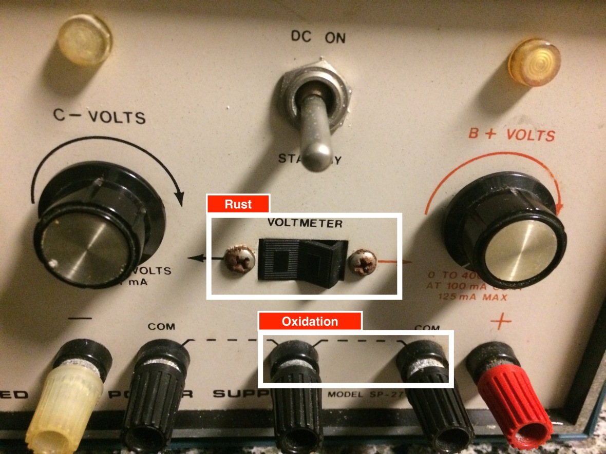
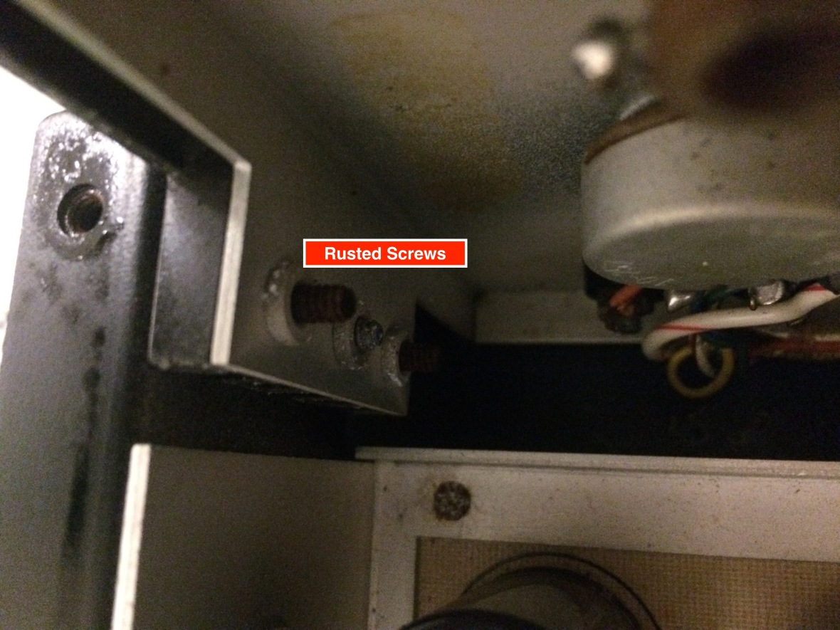
First Glance at Panel. I notice rust on the screws, output sockets have oxidation.
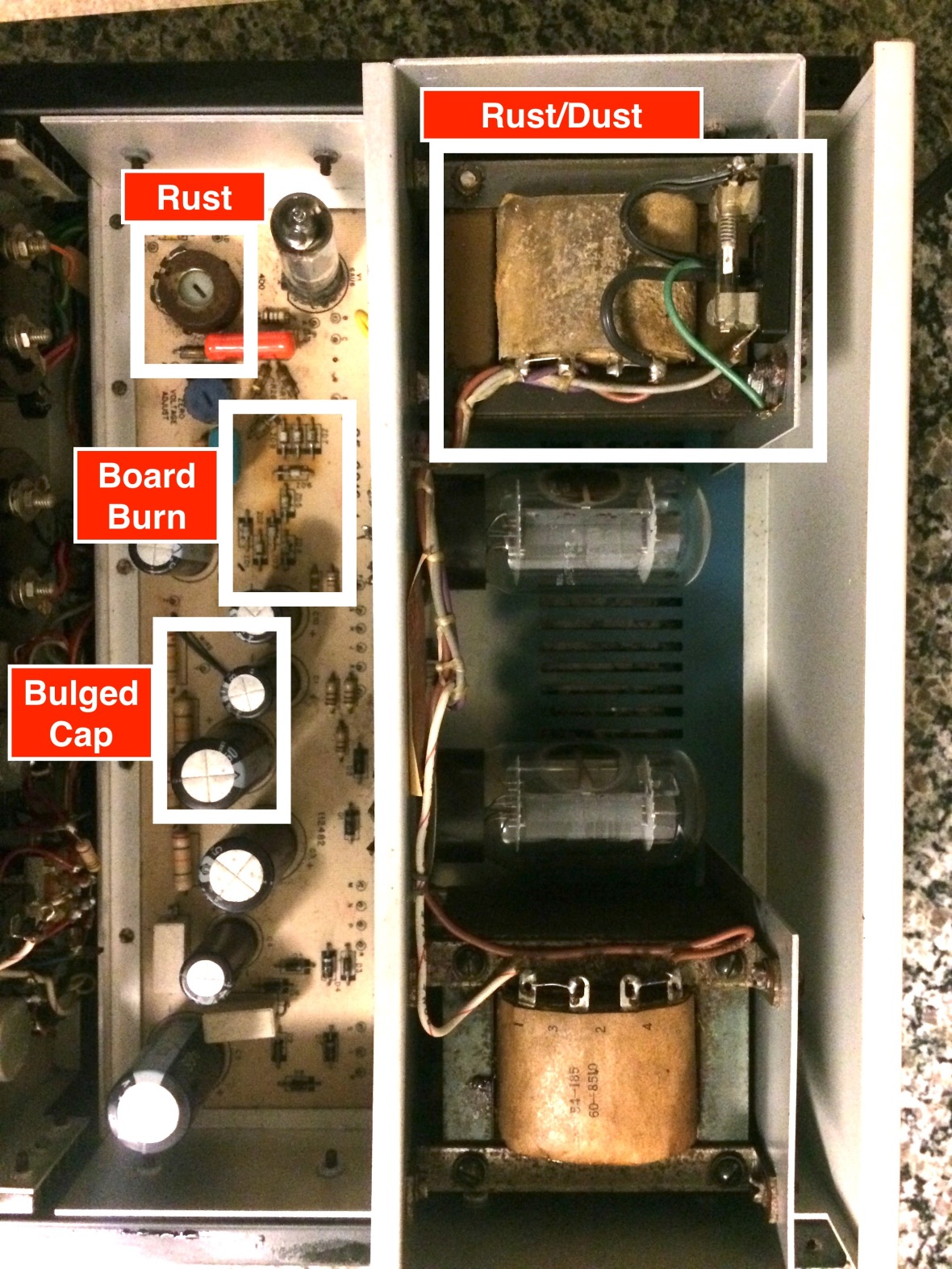
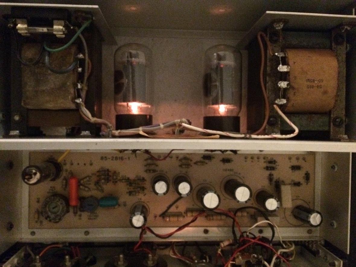
Lets look at inside, like I mentioned before, there is nothing exciting here to troubleshoot.
Typical vintage gear with leaky/Bulged caps, rusted screws. Notice the PCB is kinda burned because the person who assembled this put the zener way too close to be board. They do get hot and was burning the board. Dust all over inside as expected.
Now, first step is to remove the caps and inspect in detail.
As with any vintage gear, the capacitors – both electrolytic and paper- may/will be leaky/bulged. Physical inspection can give you some clue, ideal scenario is to do detailed testing with capacitance tester/leak tester OR replace all ideally.
Also if you observe there are not protection around terminals. I like to heat-shrink those terminals when I restore things.


Time to clean the chassis, connectors, check for cracked wiring, rust, and I did re-solder few points.
These are not factory made products. Its assembled by someone. Highly advised to check the wiring, with schematic, as there could be mistakes in the whole assembly/wiring.
Time to check the tubes out. There are only three, 6AU6 Pentode and 6L6GC beam Pentode as the main series pass regulator. For me the 6AU6 was bad, shorted. Changed it as I had it in stock. Luckily main 6L6s were good


I didn’t have the caps in stock, so ordered caps. Decided to order the best in the class as I can not take risk at 450V or wanna risk my regulator tubes being burned.
While waiting for caps to arrive, decided to fix rest of the issues. I personally don’t like rusted screws, one control trim-pot was rusted too. I cant replace the POT so repainted it, but replaced all screws. Removed the Volt meter selector switch and cleaned it too.


Time for Electrical troubleshooting. Check all diodes, as there is a possibilty of them to be bad, in case the unit was abused. For me many of the zener diodes were shorted. I assume this be due to overheating.This is a 27V Zener. The design use them in series to get the high voltage reference they need. Remember raise the Zener off the board, as much as you can to provide cooling. They do get hot.
Trip to HSC (Halted Supplies ) or Excess solutions got me those diodes ( I am in no way affiliated with neither of these).
Caps arrived too, and time to put things together.
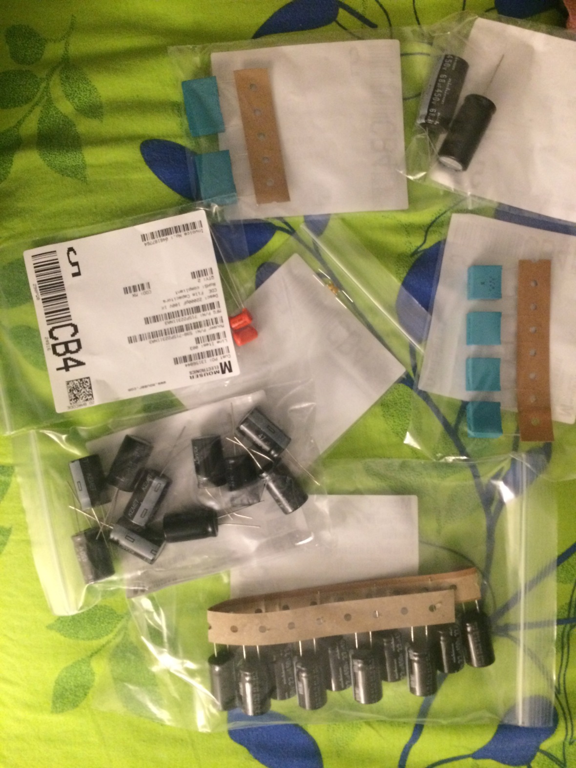
[ You will see some box caps, they are the precision 1% tolerance ones ordered for EICO 950B, check the post on that in case you wonder what that is]
WARNING
CLEAN THE FLUX AFTER SOLDERING WITH ALCOHOL. VOLTAGE LEVELS ARE SO HIGH THEY CAN ARC THROUGH FLUX AND CATCH FIRE.
Here is the rest of the process in pictures. I replaced the front panel indicator 6.3v Lamps with LEDs.


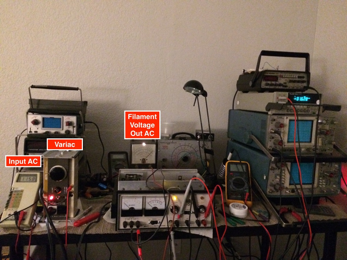
Now, time to power up. Power up first with heater transformer. You need to turn on the main “power” switch On to enable only the filament transformer and keep the “DC ON” switch in off position .
Use variac to power up slowly and ensure tubes are glowing
And confirm the Filament voltage on the front panel is delivering 6.3 and 12.6 (output will be slightly over this as there is no load). The VTVM in the rear is reading the 12.6V output from front panel.
Now time to connect main B+ transformer and monitor main output. Basically you need to keep the filament or main power transformer on for a minute or so to warmup the tubes, and then flip the DC switch to ON position. This will enable to main B+ Transformer . Again do ramp power slowly via Variac, and monitor output. You can use the built in meter or external multi meter to do this.


If you checked all components and fixed the faulty ones, it should be working like above. You can see the -output and +ve output. The Fluke output shows the +400V output.
The last picture is with a load on the +Ve rail to show the ammeter in action.
CAUTION : -ve rail is for Grid. Its regulated by the resistance of -ve voltage control Potentiometer in front panel. There is no active component involved to deliver high current. Do not connect anything heavy to it. It will burn the Potentiometer.
And here is the left over from the whole restore project.


Here is a very simple explanation of the schematic. Refer to manual for detailed explanation.
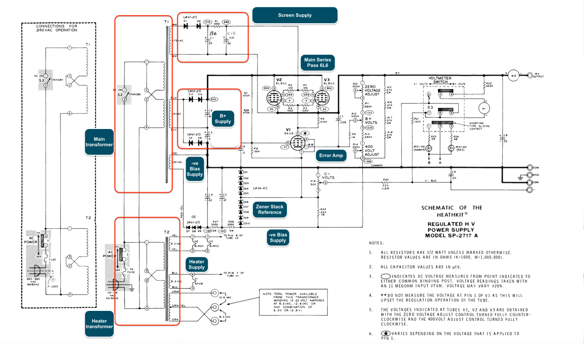
Transformer: Two main transformers. First one – T1 – for all the high voltage outputs, both negative and positive. This transformer also supplies the screen grid bias voltage for the main tubes. Second one -T2- for heater, supplies heater voltages to all the tubes as well as 6.3 and 12.6 ac heater output in the front panel.
Rectifiers : D1-D2 Half wave rectifiers for screen bias voltage for the 6L6 series pass tubes. D3-D6 – with C2-C3 is a classic voltage double, which generates the main B+ voltage, which is fed in to the regulator section. D7-D9 is the rectifier for -ve or grid or Bias output.
Main Regulator : B+ voltage is regulated by the two 6L6s, which are i controlled by the 6AU6 – which is used as error amplifier. The 6AU6 gets its regulated control voltage on its control grid through B+ output control pot R12. The output (plate) of 6AU6 drives the control grid of 6L6.
Voltage Reference : R27, R26 and the zener stack – ZD1-ZD10 is the reference source for the whole circuit, basic form of zener regulator. Regulated voltage developed across it used to bias the 6A6U at one end through the resistor network R10-R14 and R15-R18.
Regulator Control: The control grid of the 6AU6 is biased with the resistor network R10-14 and R15-R18. One end of this resistor network is connected to the Zener reference, other side to the output voltage. In case the output goes high, it will drive the 6AU6 grid more +ve, which will bring down the voltage of control grids for 6L6 to reduce the output voltage.
Bias output Control : The negative output or B- or Bias output is directly developed off from the zener stack, control by a simple pot R19
Remember, the output of -ve Bias supply is controlled by a tiny pot R19. Do not load the -ve supply, as it may burn the pot.
Back to Home Page for more restoration projects

This was a great read and you seem to know your stuff (I do not). I found this because I just came across one of these exact units at work (it JUST failed after 37 years in service), and the lab is getting rid of it. I wondered if you want it? it is in MUCH better shape then the one you describe here (not corrosion, caps all look to be in good shape). It has two extra smaller tubes then the one you show us, and they do not seem to work, but I do not know. You can contact me at xxxxxx@gmail.com if you are interested in it and some other items that you may like.
LikeLike
@LazyElectrons I’m also looking to get one of these. Is there any particular difference between the IP-17 and IP-2717? These units seem to be becoming pricier over time.
There are a bunch of the SP Schlumberger series of the same online for sales but they seem to go for $200+.
LikeLike
I dont have IP-17, but I checked the schematics online and looks like mainly its on the rectifier and VR side. IP-17 uses 0A2 VR Tubes instead of Zener in the 2717 , and also for one stage of rectification, IP-17 use 6X4, whereas on the 2717 its diodes.
LikeLike
I finally purchased the IP-17. Had my eyes set on a nearly mint condition PS-4 but unfortunately someone sniped my bid. So, had to pay a little more and got an IP-17. The supply was used in a college lab. Those guys were downsizing their inventory. Did a re-cap and had to use some CRC contact cleaner to un jam the C- knob. It works fine but I noticed something strange.
It maybe that the IP-17 is just like that or it’s malfunctioning, not really sure. I noticed that when both the C- & B+ voltage knobs are at min and the DC switch is turned ON it rises to like 25V and then slowly drops back to 0V in a few seconds.
So, now if I switch back to STANDBY then the voltage quickly goes to like -14V then rises back to 47V and then slowly drops back to 0V.
Is this a common phenomenon with the IP-17 or something is going bad inside?
Here is a video of the issue I have shot an posted for better understanding. I have a feeling it could be the caps that are discharging slowly?
In the first part I’ve used a load resistor to see if it is able to absorb the voltage fluctuation.
Also I found the same issue on another video posted by another person sometime ago but on an IP-2717A, timing from 3:43 to 4:24 to see the issue:
Does your unit exhibit something like this?
LikeLike
Mine does not have this issue, but 2717 uses Zener and silicon diodes instead of 0A2 VR Tubes and 6X4 rectifier, so cant compare at all. Remember that the VR Tubes have a different starting and maintaining voltage. And it is depended on ambient light too (some older military tubes have radio active materials inside them to maintain constant starting even in total darkness apparently !!!) . What I feel is, once you power off the input, the caps discharge and dips below a certain voltage causing VR to go off (below sustaining voltage) and the regulation dies, hence the output just follows the capacitor discharge, until the series pass tubes totally cut off, OR there is a C8, 20uf Cap at final output, may l you are seeing it discharging once the tubes are cut. Try disconnecting that fella and check.
LikeLike
But in the second youtube video its a 2717 with the same phenomenon. Yes, in my unit it takes a few moments for the VR to kick in. Mine is a Sylvania 0A2 with radioactive symbols on it. You might be right about the cap discharging part since when I tried with a load connected they don’t jump around too much like at no load but still the fluctuation is present. I guess that could be bad if a real circuit is left connected. I try today by disconnecting and see how it responds this time.
LikeLike
Thats interesting, put a voltmeter on the input and output side of the regulator and try the same experiment, so that you find out which side is causing it. Reg Radio active tubes, be careful, there are different opinions about them all over the web, being highly dangerous to being trivial. I have a bag full of OA3s and OB2 and 5651s right in my bedroom for months, so if I die soon, you know why 🙂
LikeLike
I found a 2717A recently that looked in very nice condition, but there is no C- voltage output. Everything else measure as it should. Any suggestions as to where the problem might be would be greatly appreciated. Thanks!
LikeLike
Check for C- @ the Pot, one end of the pot should have -ve voltage. If yes it is the POT, if not check at R26 and move back in steps until you can find the failed component.
LikeLike
Thanks for the quick reply! I’m very new at this and sometimes need the terms explained to me. I am not familiar with -ve voltage. A google search was not successful. Would -ve voltage be measured the same as DC voltage? That was the setting I used on the multimeter. Sorry if that is a bonehead question.
LikeLike
OK, making progress! Figured out -ve voltage is just voltage with a minus sign on the DVM. Checked the pot and it is good, then noticed the resistor on the center tap (R20) was completely cooked and the back of the pot was smudged from the smoke when the resistor blew. Here’s hoping that is the only problem. Thanks so much for pointing me in the right direction.
LikeLike
C- is used for the grid bias supply for vacuum tube circuits. Hence it’s -ve. Most likely someone overloaded the -ve output. Check your -ve output pot too. It could be damaged as well. FYI – the -ve output is rated for 1 mA.
LikeLike
Turns out the resistor was a wire wound. I was only able to fine a “normal” resistor of the correct value locally. Would it be acceptable to use it, or should I order a wire wound? What would be at risk if I used the the normal one?
LikeLike
Turns out I was misinformed about the wire wound resistor. Installed a carbon one and the thing works like a champ! Did not even need to calibrate it. Thanks again for your help.
LikeLike