This is another strange looking instrument from 1950s era. Took me a while to understand what it is really, so here is the summary –
It is a VTVM + Normal Volt Meter. Which means it can operate without power as well with trade off of low input resistance.
- Center Zero VTVM – Yeah, Zero in the center of the dial, you can read + and -ve without changing the probe polarity or Switch
- DC VTVM – Max volts – up to 6000Volts
- Traditional Analog Multi Meter (AC/DC/mA & dB) – No need for Power for normal measurements. For this left side of the dial is zero, like traditional meters
- HV Volt Meter – up to 6000 Volts, both on normal meter and VTVM.
- HF AC Volt Meter
- Gig Ohm Meter – up to 2GΩ.
- Input resistance 13.3MΩ till 600V, 26.6 M till 1200V and 133 MΩ@ 6000v Input in VTVM mode, 1kΩ/Volt in normal volt meter mode.
- Can do up to 60KV with Additional HV Probe !
- Up to 12A Ammeter
- 70dB for output (AC/Sound/xmitter output) measurement
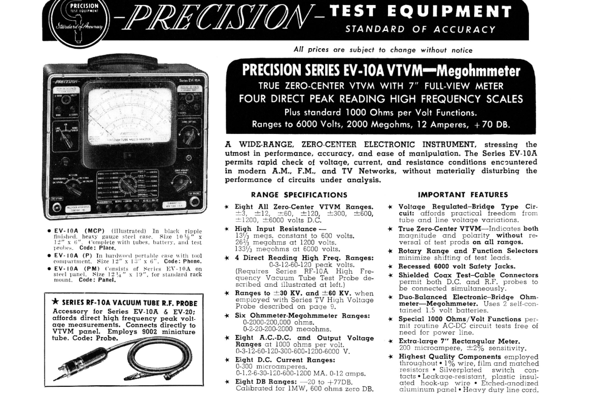
Here is the page from the 1952 catalog
Here is a video of the restoration
Details of the restoration are logged below.
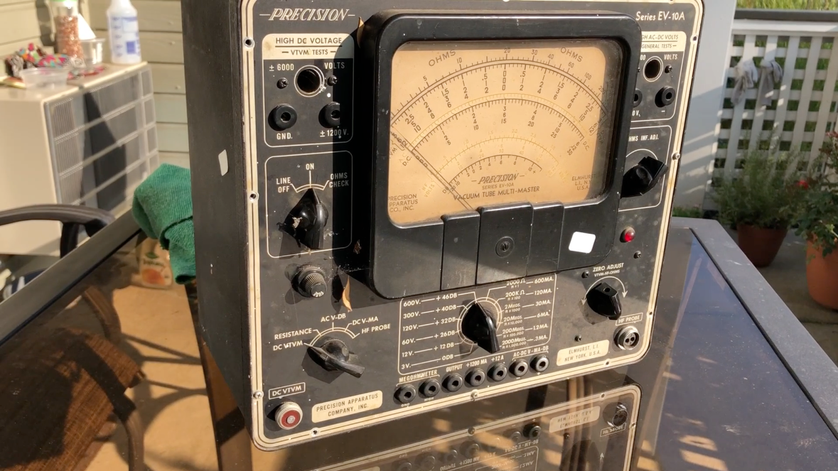
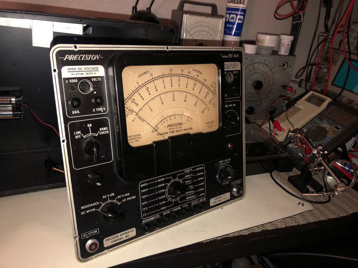
So here is how I received it –
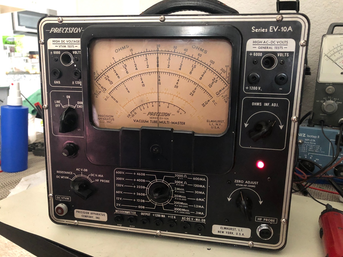
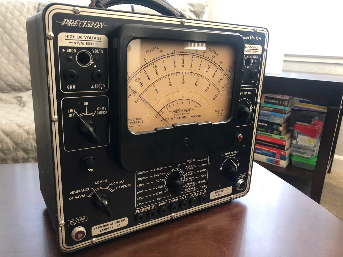
Here it is now, after restoring, showing
the center zero VTVM in action.
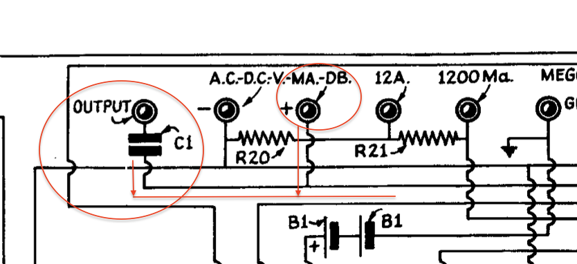
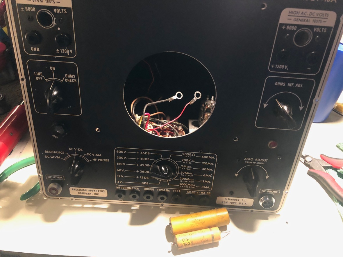
Here is the map of front panel for the different functions, including VTVM and normal voltmeter inputs.

Resistance/Current/dB/Output measurement jacks.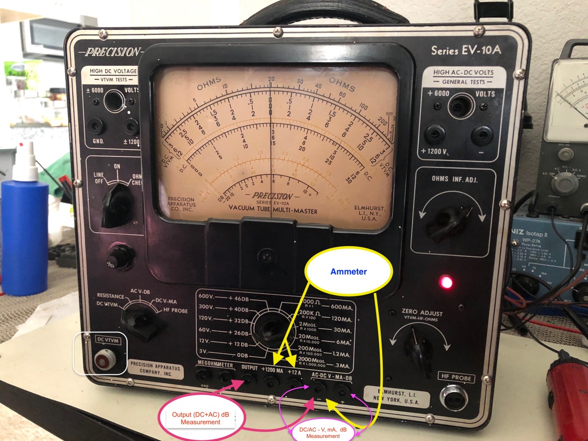
The difference between dB and Output jacks is the presence of blocking capacitor C1 in output measurement Jack. dB measurement assumes direct sound AC input – eg from the speaker terminals – where as “output” measurement jack can be connected directly to the plate of the output tube, and there is a built in .01µF/600V capacitor in the meter to block the DC B+ on the plate.
Restoration
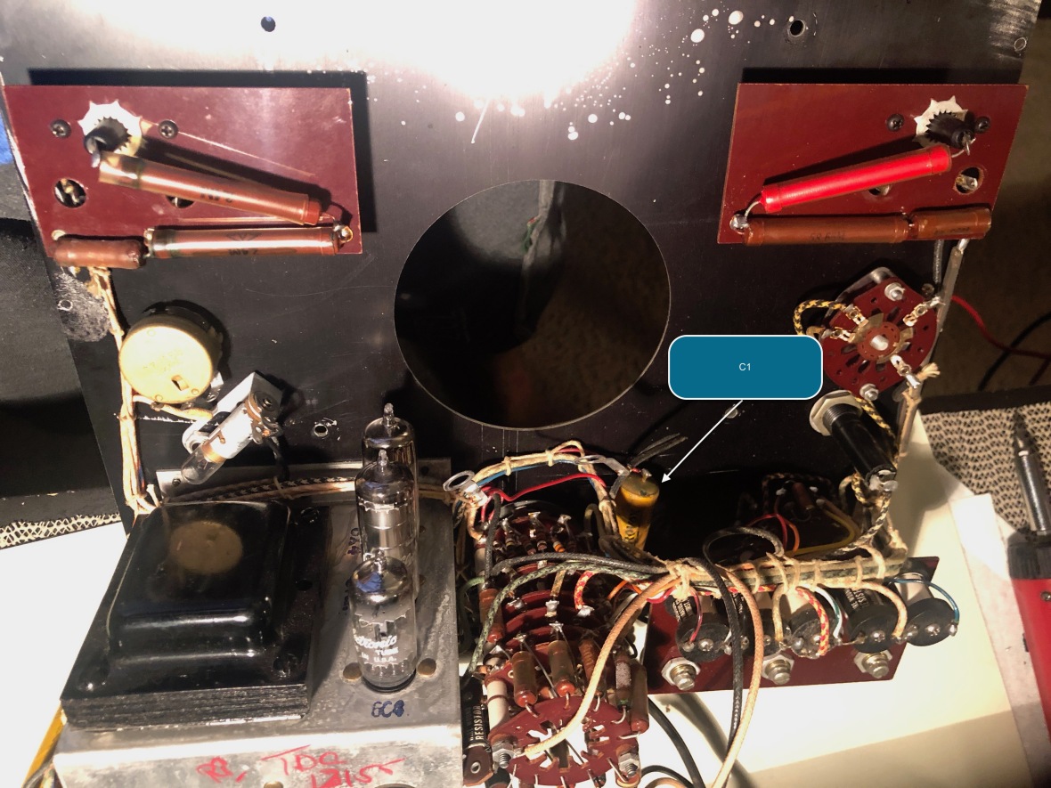
Very simple process, unless the tubes are bad. Just two capacitors to replace. one is the C1 in the above picture – the DC blocking cap.
And the replacement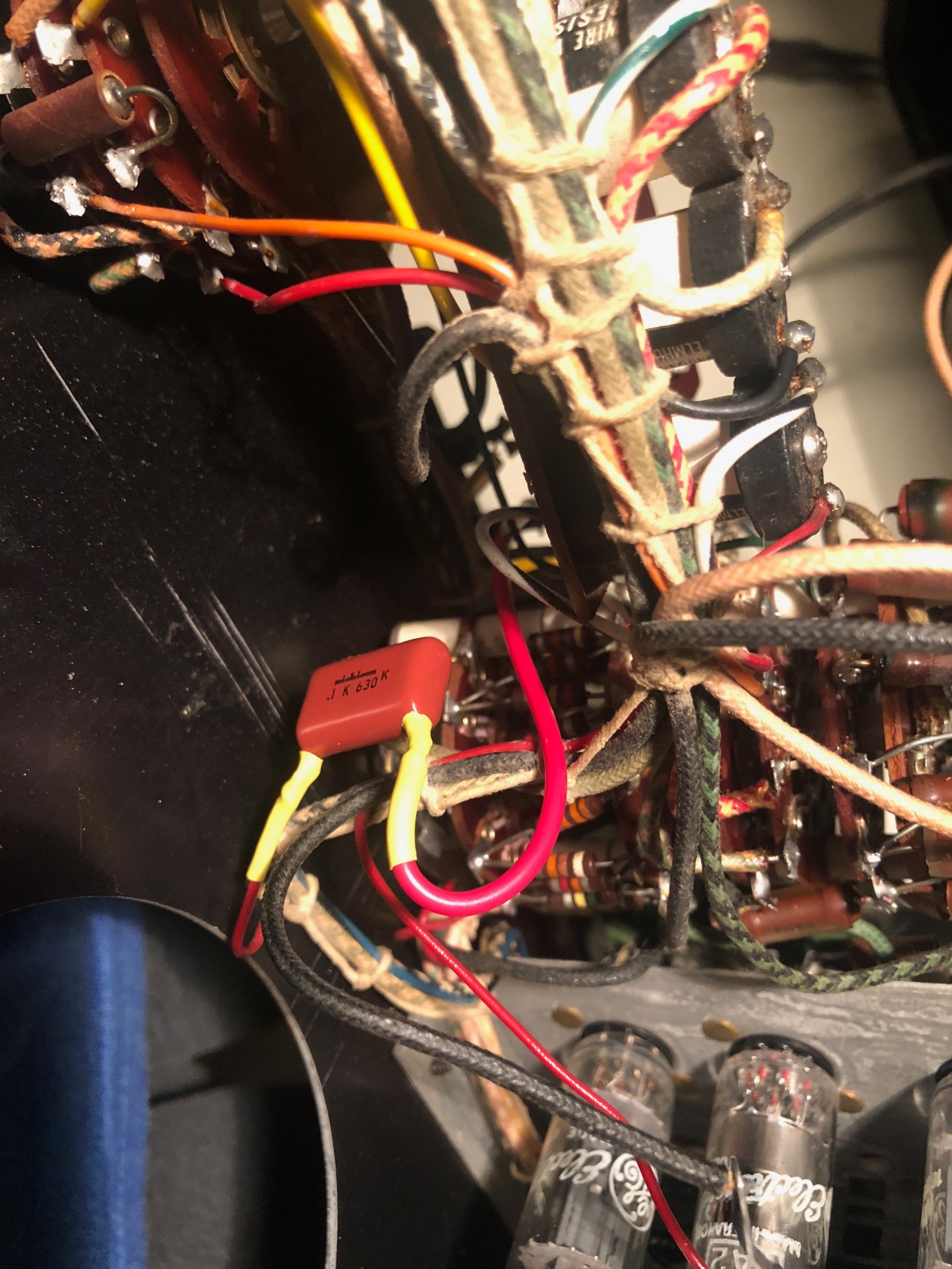
2nd is the main power supply filter cap,
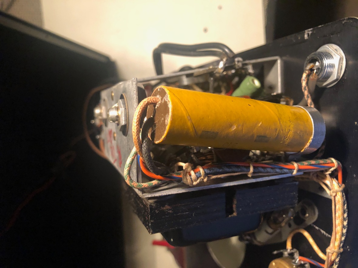
And the replacement,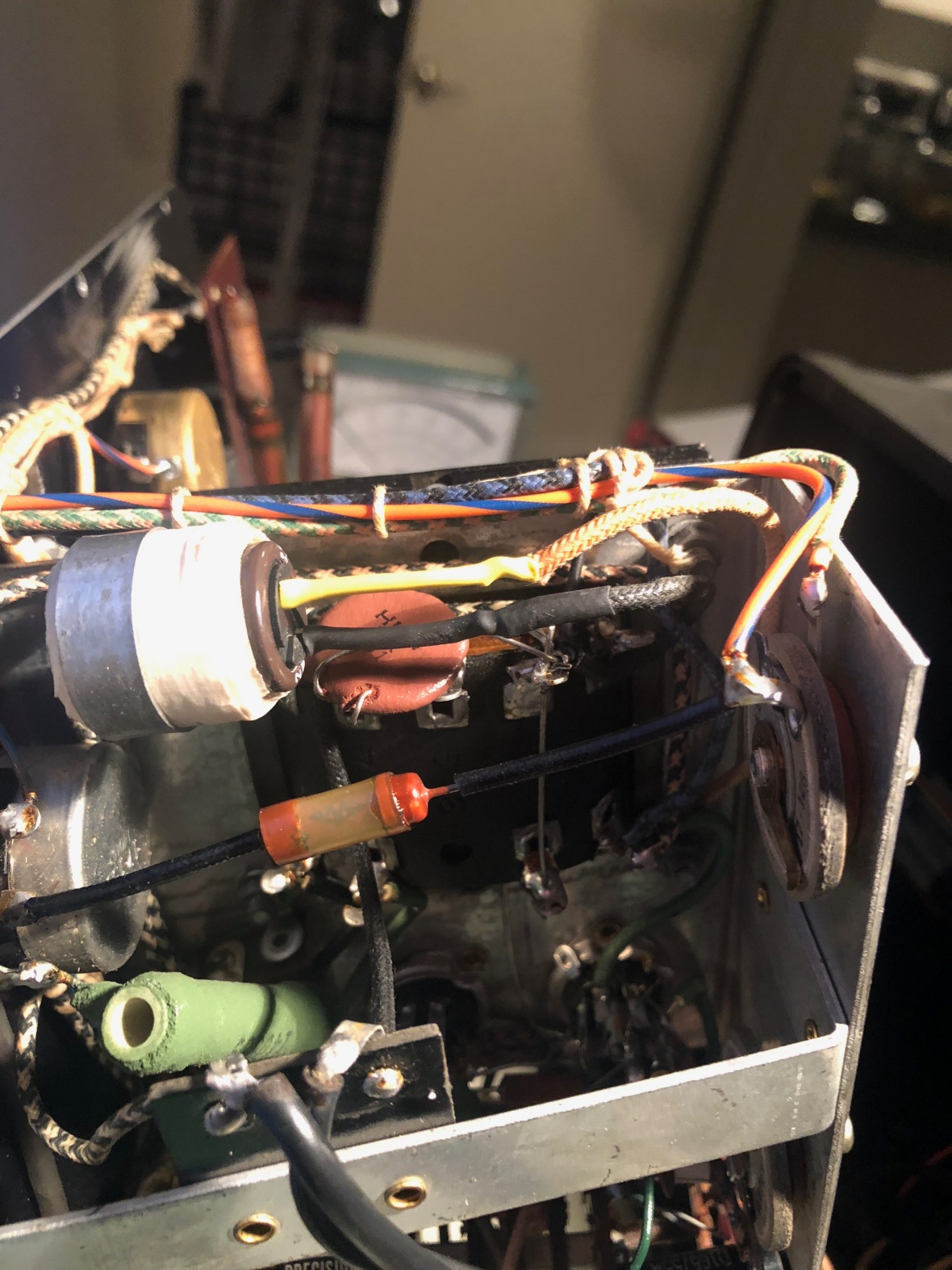
I removed the meter movement to clean it, also showing the old caps
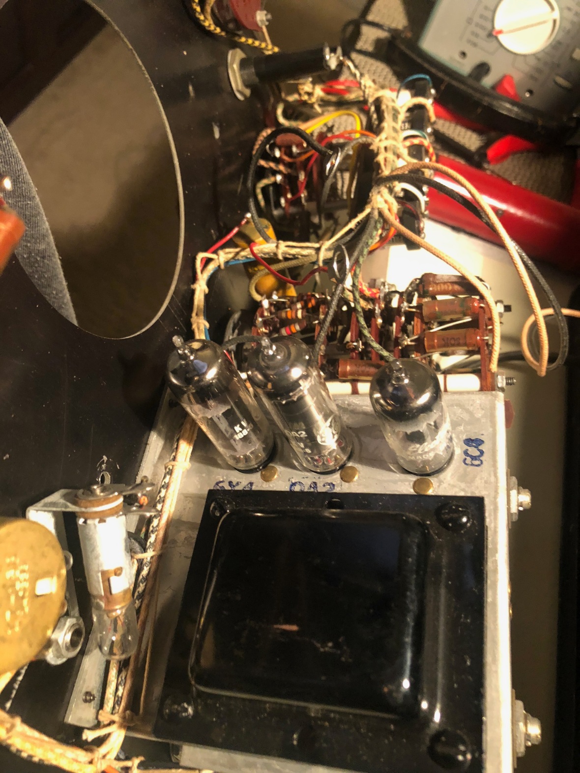
Few pictures of internals – Note: Meter movement is removed for cleaning.
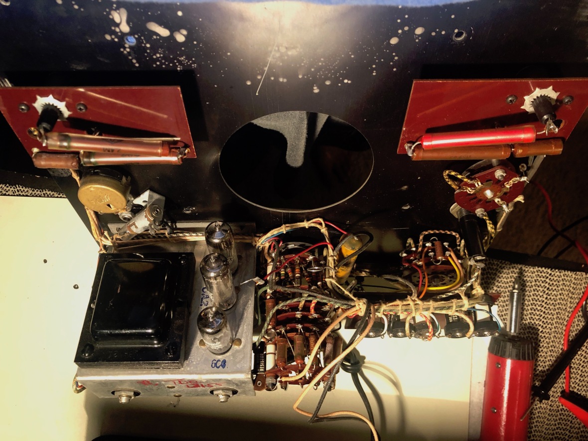
Close look at the tubes, 6C4 Triode, OA2 regulator and 6X4 rectifier.
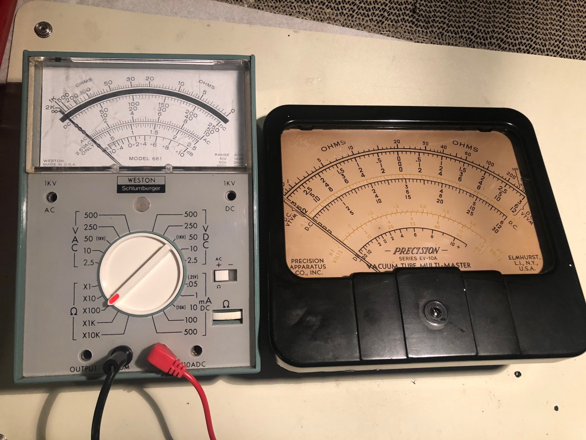
Dial is substantially large, comparing it with a complete multi meter
Here is the front panel removed, you can see the 1.5v X 2 cells inside the cabinet, used for resistance measurement.
And here is the unit after cleaning and reassembly.
Here are few measurements
Normal multi meter mode – Voltage (DC) Measurement.Note: Power is off -. Input terminals are the pin tip jack – labeled DC-AC-V-mA-dB
DC mA – Note the series resistor.
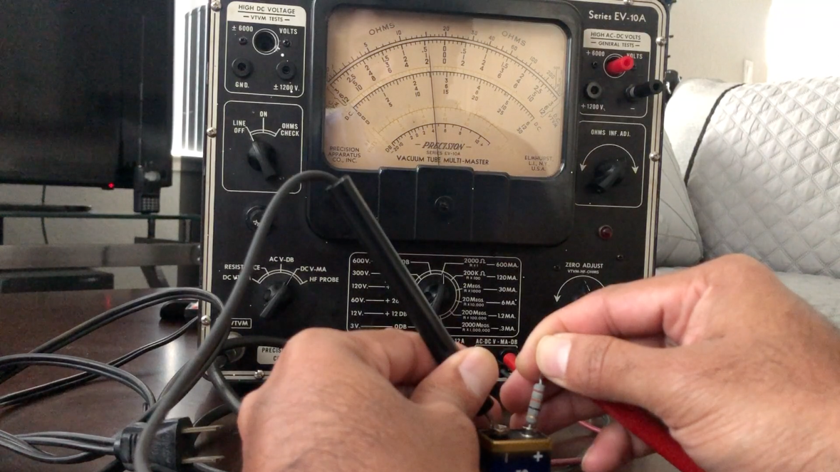
Now to VTVM Mode, Power on and use VTVM Probe.
VTVM in positive polarity ie. Probe +ve goes to battery +ve and -ve to battery -ve
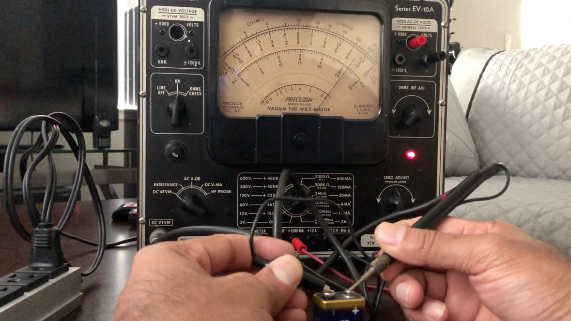
VTVM in negative polarity ie. Probe +ve goes to battery -ve and -ve to battery +ve
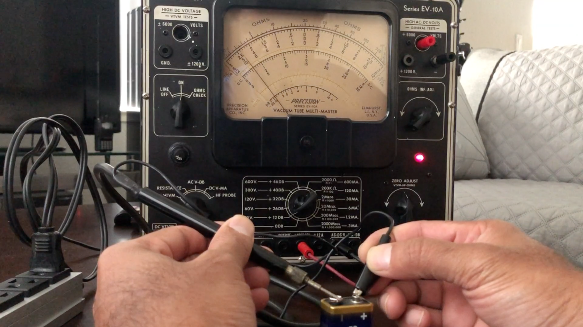
As center is zero
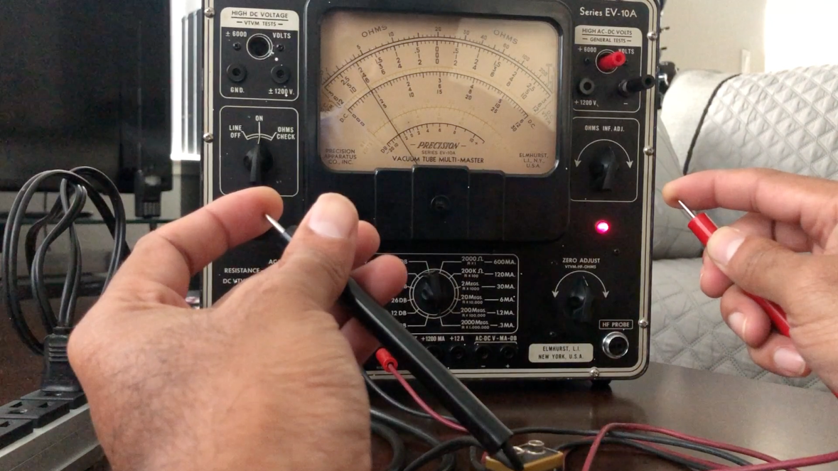
And quick resistance check in 2GΩ range.
Thats it. I did not calibrate it as the readings were “kinda of ” close and I did not want to poke around. May be some time later.
Disclaimer
I have no commercial affiliation with any of the products/organizations/individuals mentioned in this blog.
The information provided here is for educational purpose only.
You are free to distribute this as long as it stays original with all information as is here and it is free and you don’t scavenge any tubes from any scopes or this blog.
NO electrons were harmed during the repair/filming of this instrument restoration. All free electrons found inside the unit were rehabilitated to the nearest vacuum tube.
NO EXTRA SCREWS OR PARTS WERE OFFICIALLY FOUND AFTER REASSEMBLY. UNOFFICIAL EXTRA ITEMS WERE DISPOSED OFF SECRETLY AND DECLARED AS “EXCESSIVE ASSEMBLY” DURING MANUFACTURE.
Please do report any errors or stupidity.
=== THE END ===
Back to Home Page for more restoration projects

Fabulous article. Good humour too. Thoroughly enjoyed it. I tinker too. Occupational hazard.
LikeLike
Thanks Andy
LikeLike
Really helped me understand how to use this VTVM. Do you have a schematic you could share, I am trying to fix the same unit I just acquired. Thank you
LikeLike