Recently, a friend of mine handed me a spectrum analyzer as a project to fix it for him. This is just one among the several ones that he owns. Since my habitat is now filled with more scopes and meters than actual things that I need, I decided to welcome this boy and introduce him to my other pets and try and fix it for him.
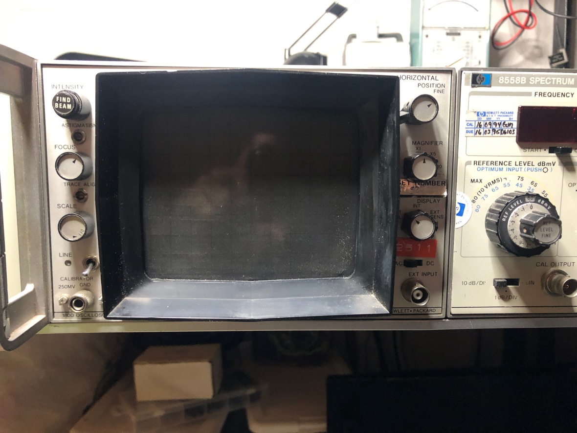
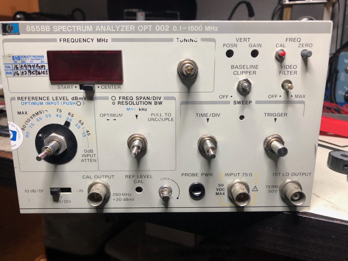
HP180D is just an XY monitor frame, which means it’s just a CRT, HV circuit, horizontal amplifier and a power supply. The plugin inserted into the slot drives the vertical deflection plates directly and signal to the horizontal amplifier comes from the plugin as well. In short, 180D is just an XY monitor as I mentioned. It could be an oscilloscope, spectrum analyzer, stethoscope, stereoscope, rocket launcher, whatever, depending on the plugin that you insert. In this case, it came with the 8558B spectrum analyzer plugin.
::SAFETY FIRST ::
THESE INSTRUMENTS CONTAIN HIGH VOLTAGES INSIDE THEM. DO NOT ATTEMPT TO REPAIR/OPEN/OPERATE/FOLLOW UNLESS YOU REALLY KNOW WHAT YOU ARE GETTING IN TO. THERE ARE DEADLY VOLTAGES INVOLVED AND IT CAN KILL YOU.
THERE ARE BETTER WAYS TO DIE IF YOU ARE UP TO THAT.
Even if you are familiar with electronics, be very careful when you work on something like this, a maximum potential difference of 100V DC is used in this equipment . HV power supply and CRT potential up to 15000V DC.
DO TAKE CARE.
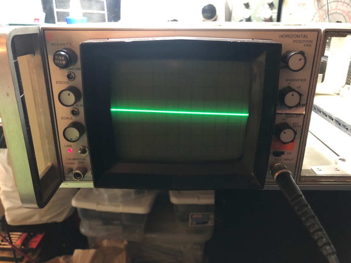
The first problem was that there was no sweep on the CRT, and the display was a small tiny trace on the bottom right corner of the screen.

Here are some more pictures of the unit –
CRT and controls
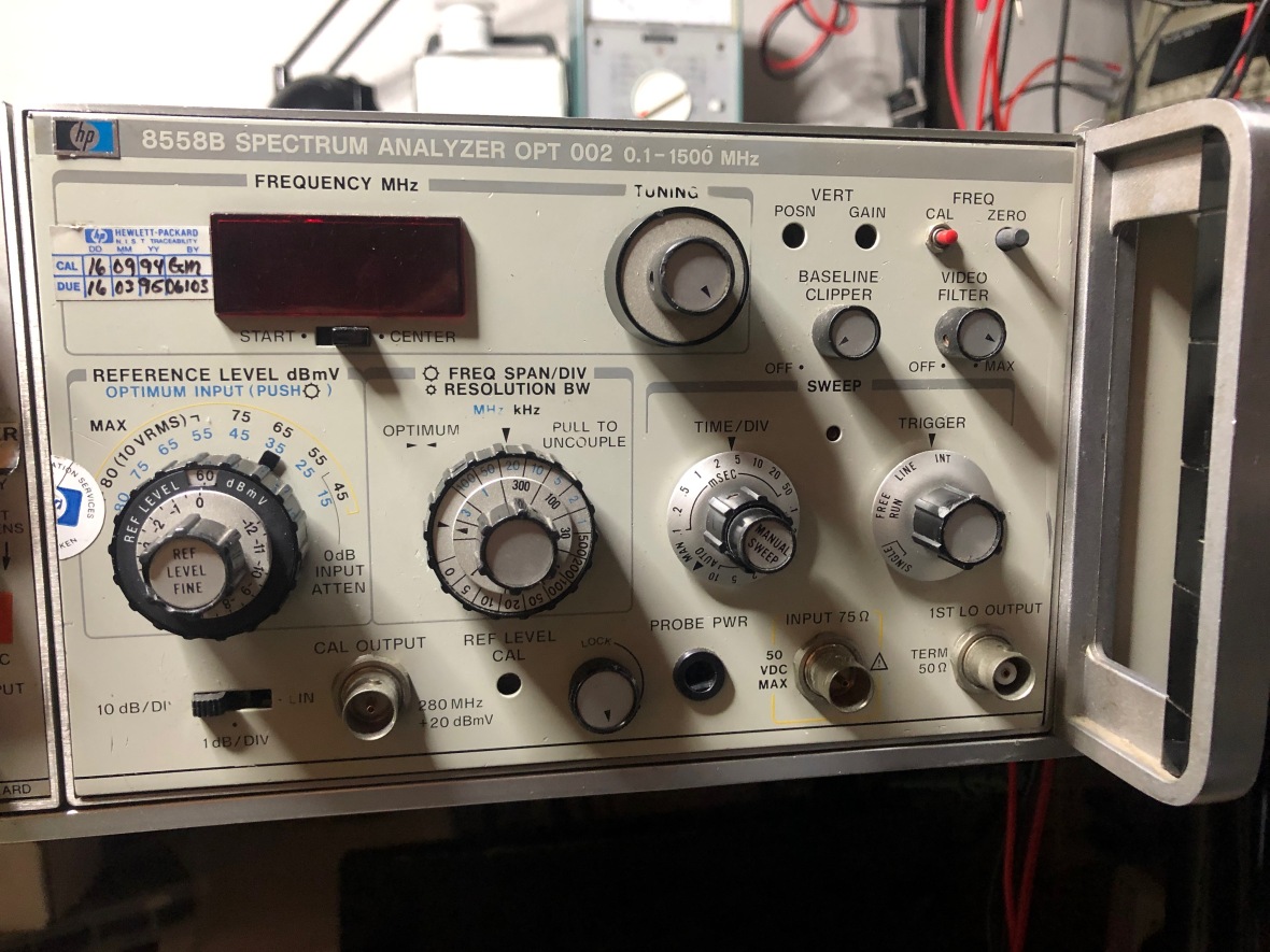
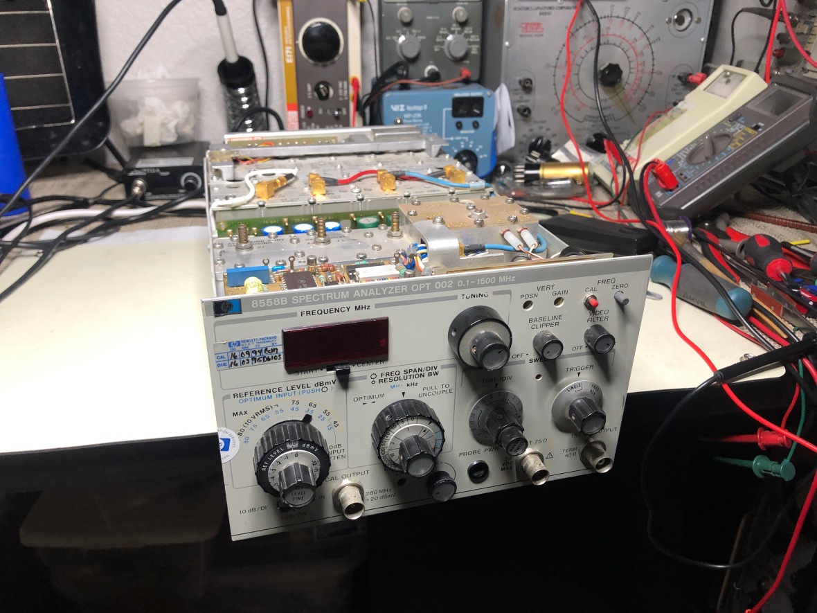
the 8558B Spectrum Analyzer Plug-in
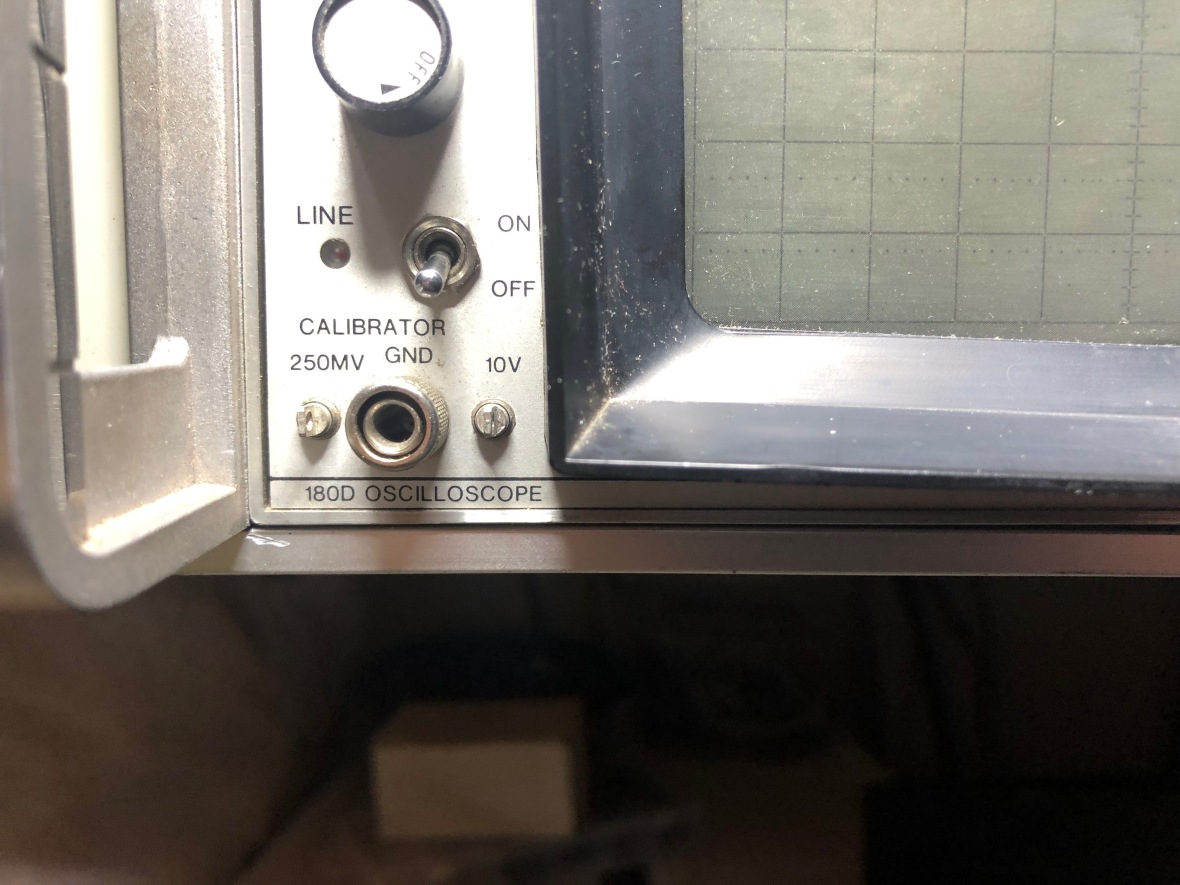
You need to search to find the main frame model number, not sure why they decided to mark it all the way down and call it an oscilloscope, may be more scope plug-ins exist than spectrum analyzer ones?
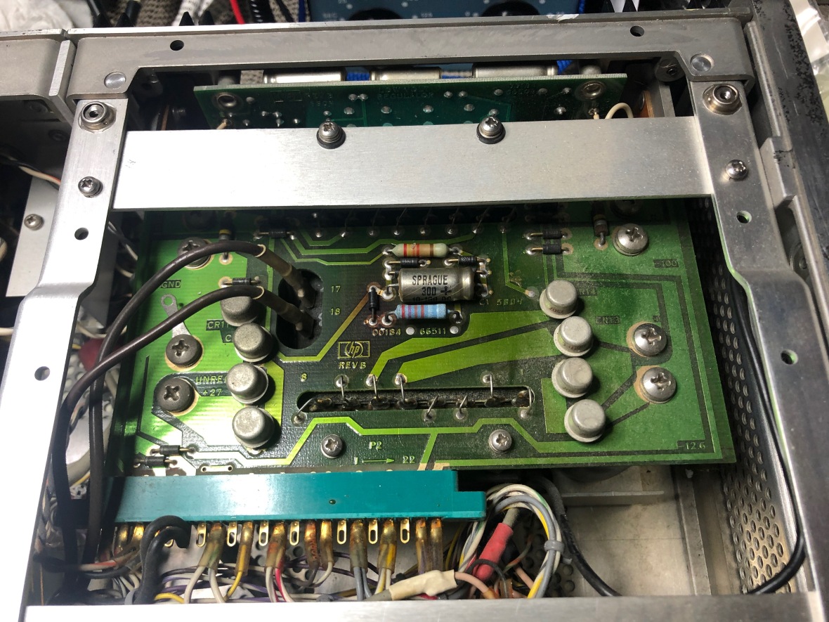
The top cover is removed and you can see the nerves of the spectrum analyzer plugin. Bottom side is HV and CRT. Top left is the low voltage power supply.
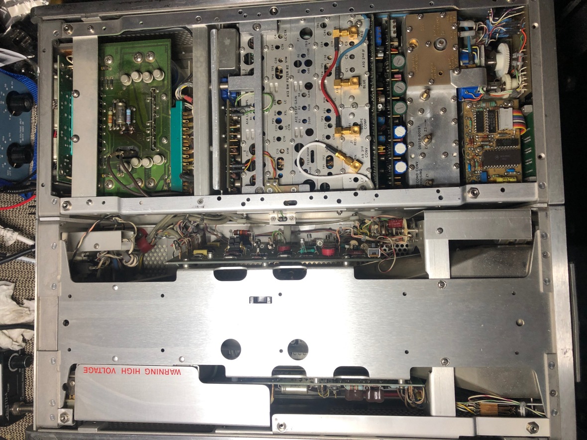
Close up of the power supply rectifier board. You can see the zener is cooking the PCB. I have seen this in many HP gear.
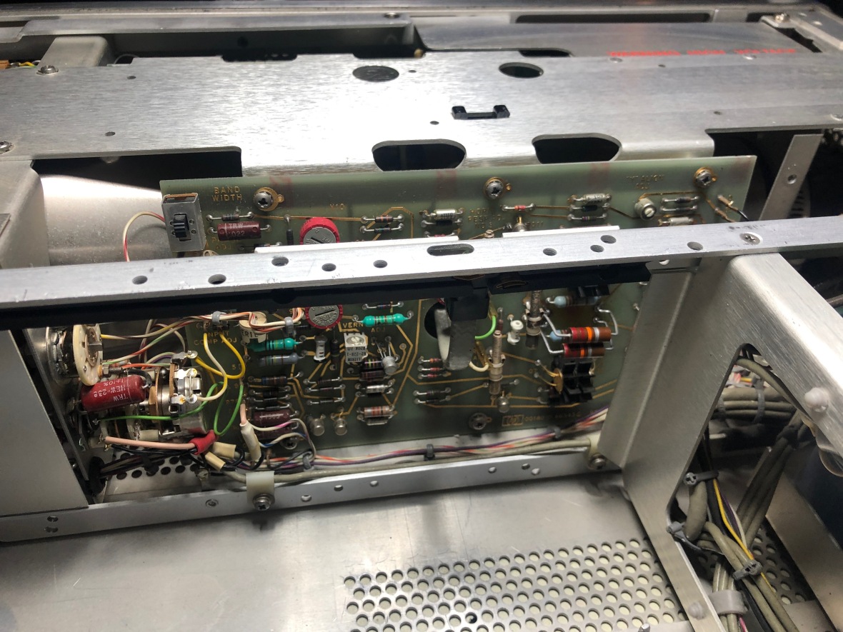
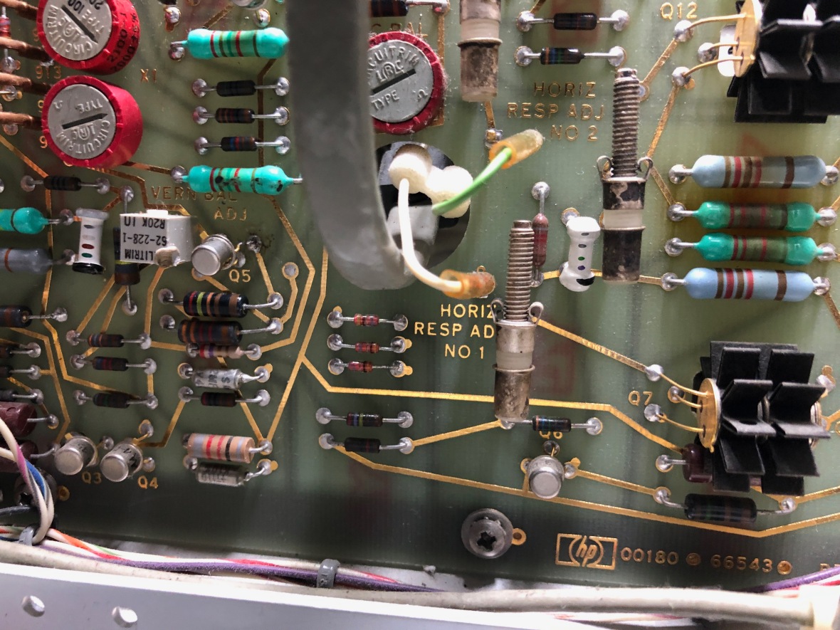
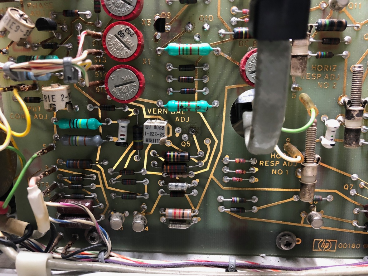
Here is the horizontal amplifier board. Mounted vertically between CRT and plug-in bay.
Oh, forgot the power supply regulator, it is behind the chassis, can be accessed by removing a covering plate. Standard linear regulator referring to single regulated source rail. +100, -100, +15 and -12.6V outputs. Nothing fancy here, very typical power supply design… series pass, current sensing, and zener based reference.

I could not find any test points for outputs, am I blind?
As always I do a detailed visual inspection, kind of strip search of the whole unit for clues, traces of other intruders who were in before. It always helped me with troubleshooting. I typically photograph these to document. Also, many times, it helps to put things together or understand more about the instrument. In the past I have discovered many UFOs (Unidentified Foreign Object) including screws, pills etc, mostly inside the large scopes like Tek 500 Series (Check my 547 and 549 Blog for examples)
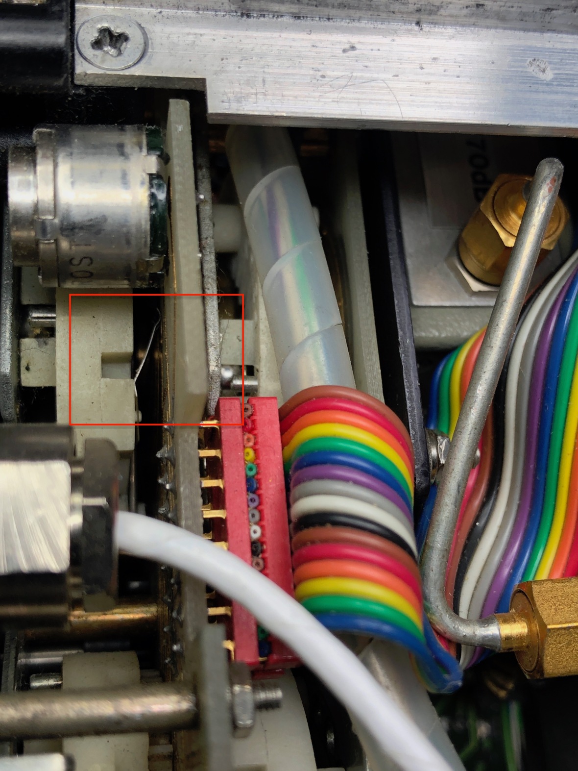
This instrument also had its share of extras inside it, but one simple RF shield or spring load sort of thing, sitting on the edge of the chassis -when I removed the cover.
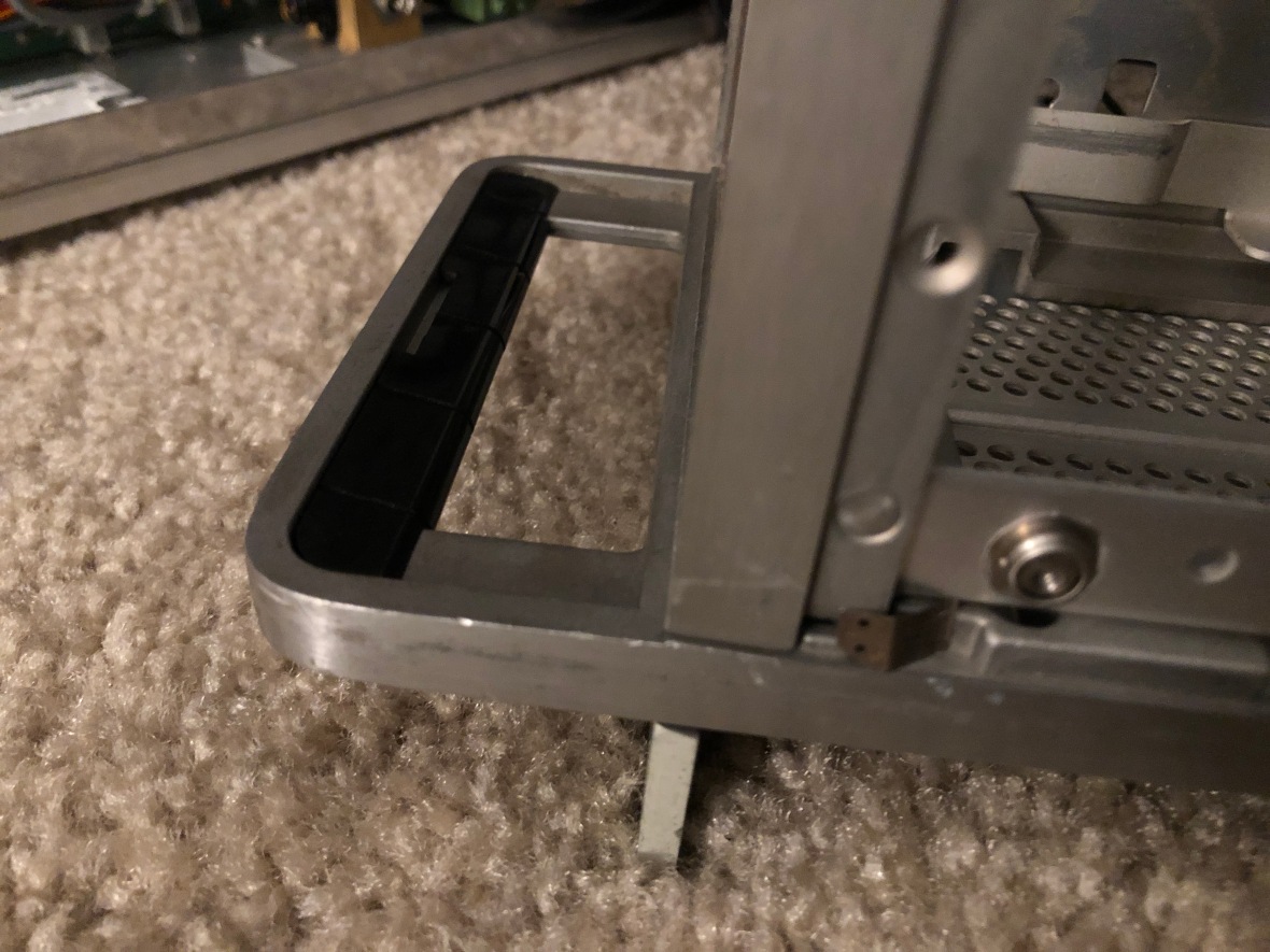
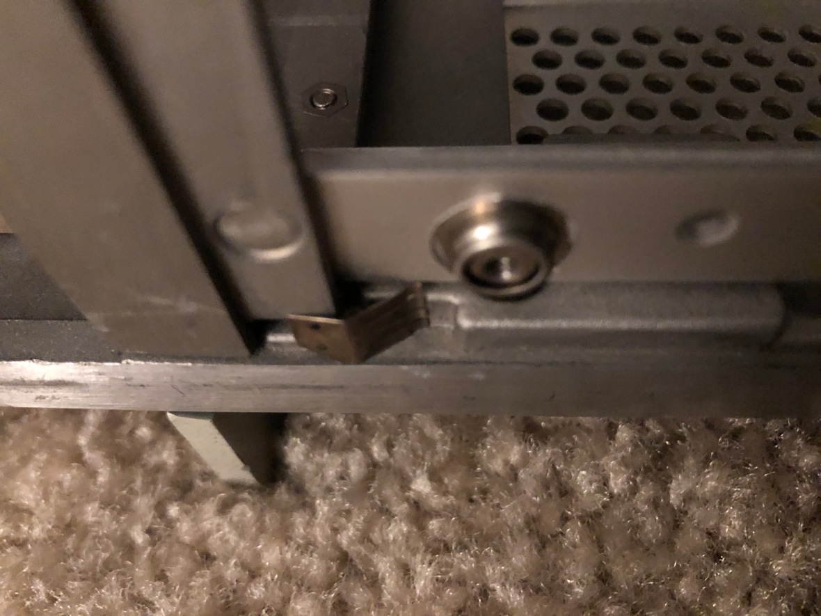
I was so happy that I didn’t get inside the board and shorted things out. It fell to the floor when I moved the chassis and was hard to trace from the carpet.
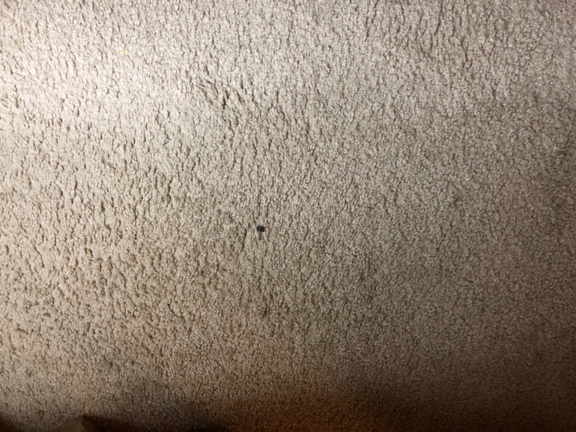
Here it is. 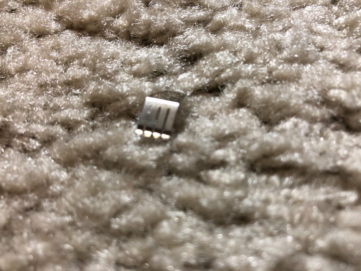
Now it’s time to start fixing.
I quickly checked the sweep output signal from the back of the unit and that was dead, which means the plugin is not providing any sweep. Interesting to note that the sweep output is directly connected to the plugin and not buffered via the horizontal stage.
See the block diagram from the service manual below – 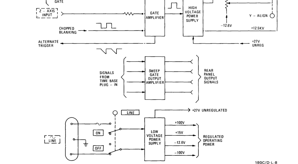
Since we already know the spectrum analyzer plugin was bad, I kept that aside.
On any modular instrument like this, I would first confirm that the main frame is all good, before jumping to the plugin, which meant that the first step was to verify that the main frame 180D was all working.
I verified all the power supply voltages, and they’re all within limits. Nothing caught my eye during the visual inspection either. No one has been inside this guy before. The usual stock of dead animals, aliens and dinosaurs were there to greet me. I also highly suspect that it was the suicide site of a poor lonely spider.

Even before proceeding any further, I found the first problem. There was no power on indicator. It was dead. I hate to see instruments which don’t tell you if it is on or off, as during troubleshooting, power on light what I look for before fingering to test if the HV is working -:D
So here the 4.5V lamp was dead –
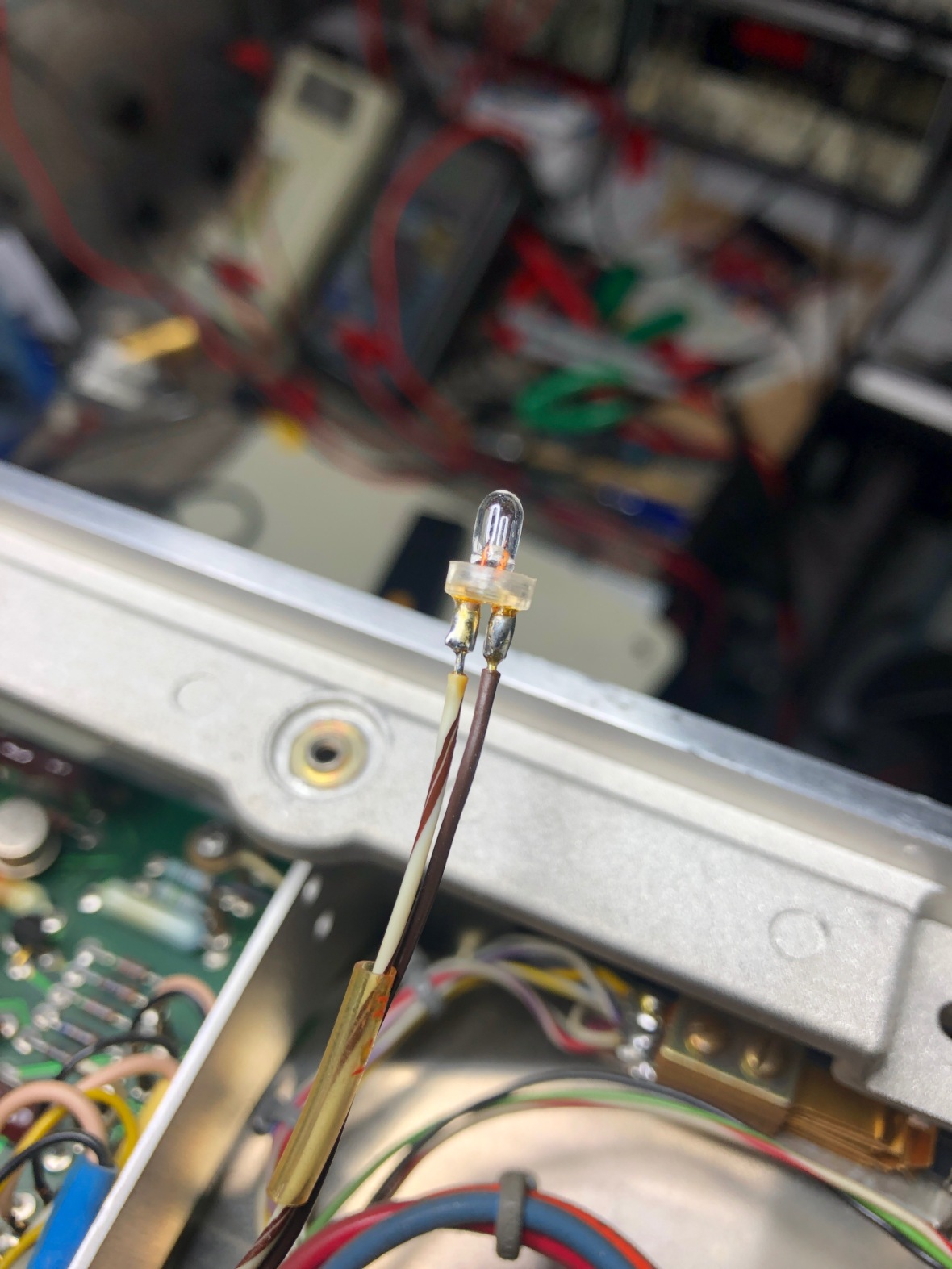
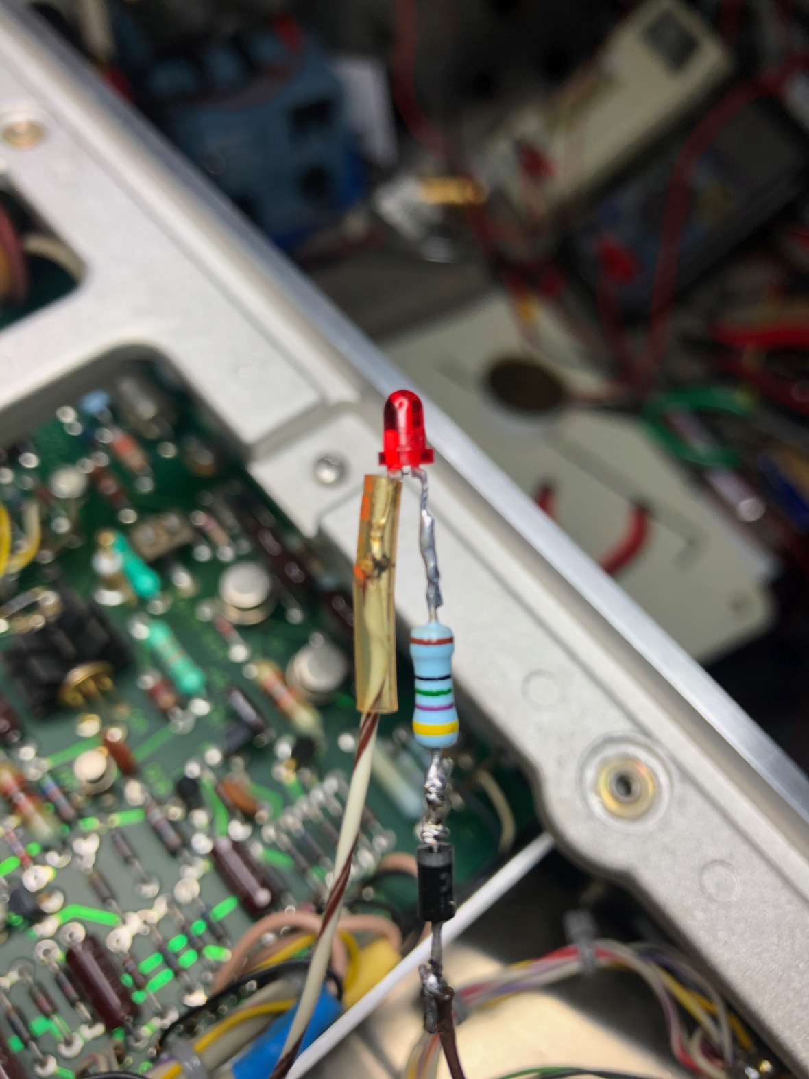
Since I have been labelled as vacuum tube guy, decided to go modern to change my image and decided to attach a LED. I didn’t want the LED to emit all the possible spectrum to blindfold the spectrum analyzer operator, so did a 475Ω resistor to keep it as dim (~10mA) as possible, still lit.
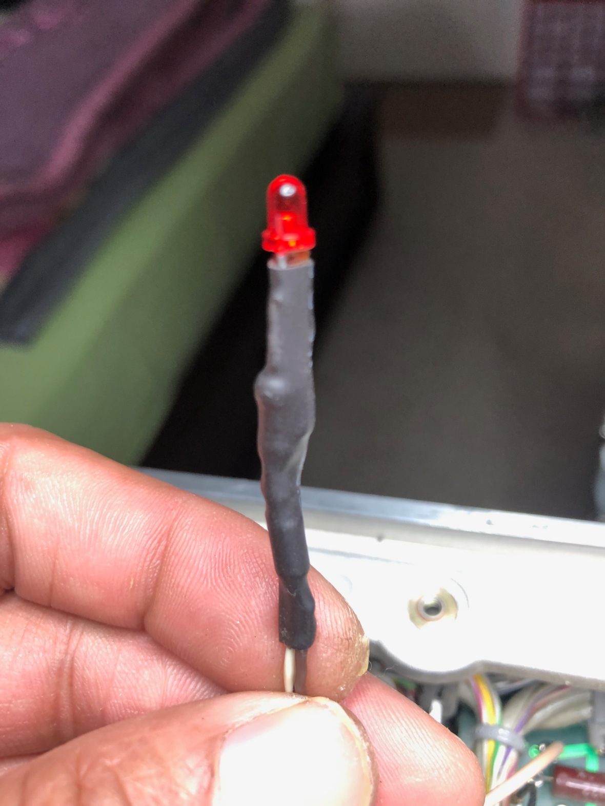
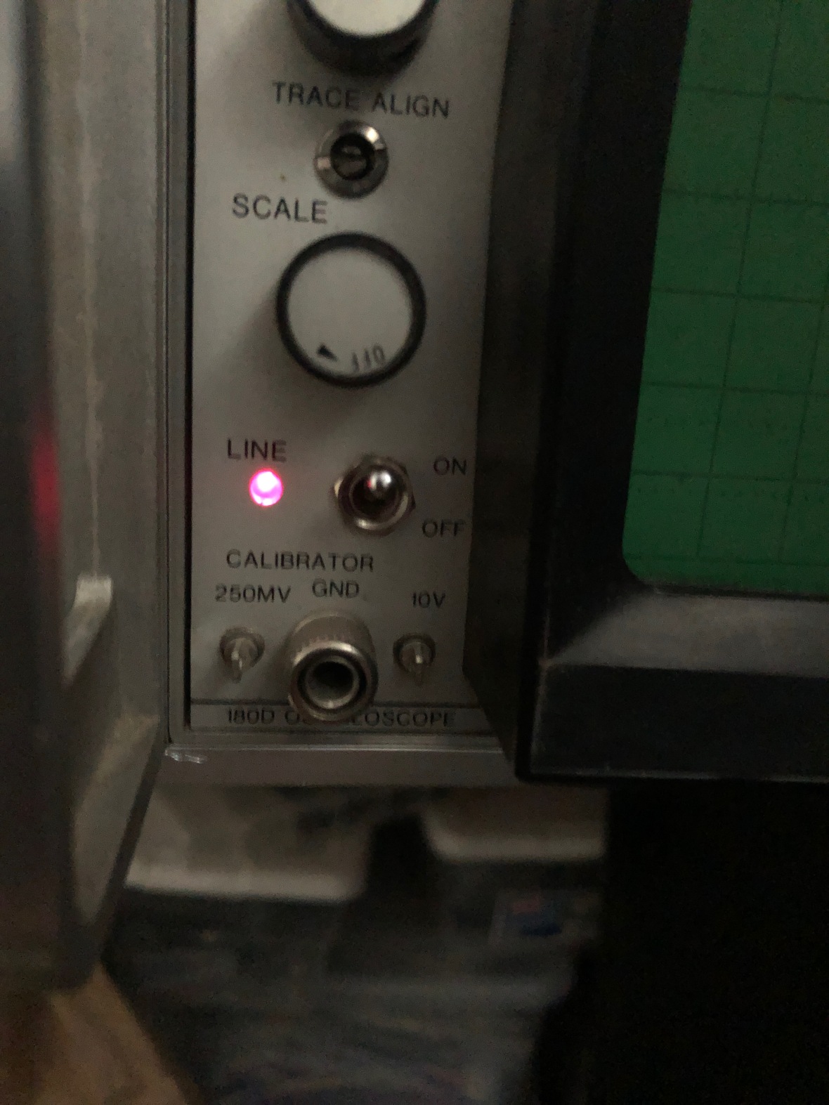
First fix is done, power on indicator is alive.
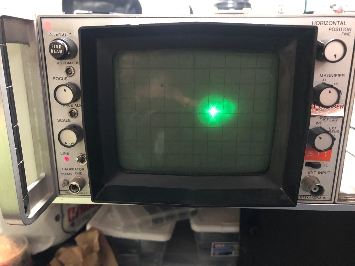
Now to the next step, on units like this, the easy way to check the main frame is by connecting external horizontal input. Vertical is driven directly from the plug-in. As suspected, there was no trace on the screen. H- position control was moving the trace less than 1/4th of the screen.
Typical first step, is to disconnect the CRT plate connectors from the H-Amp board and see if you can find the beam on the screen. Here it is, after disconnecting the deflection plates from the H-Amp board –
Here are the H deflection plate connectors on the H-AMP Board.
So basically, the H-Amp is dead or faulty. The easiest way to troubleshoot is to inject a signal on the external input and trace its path.
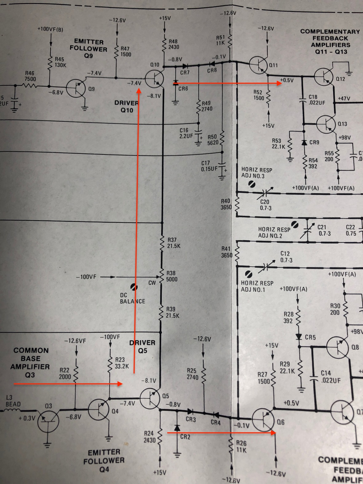
The signal comes in via a CB buffer Q3 and then to emitter follower Q4 and finally to paraphrase (Phase inverter) amplifier Q5 and Q10 to drive the final stages.
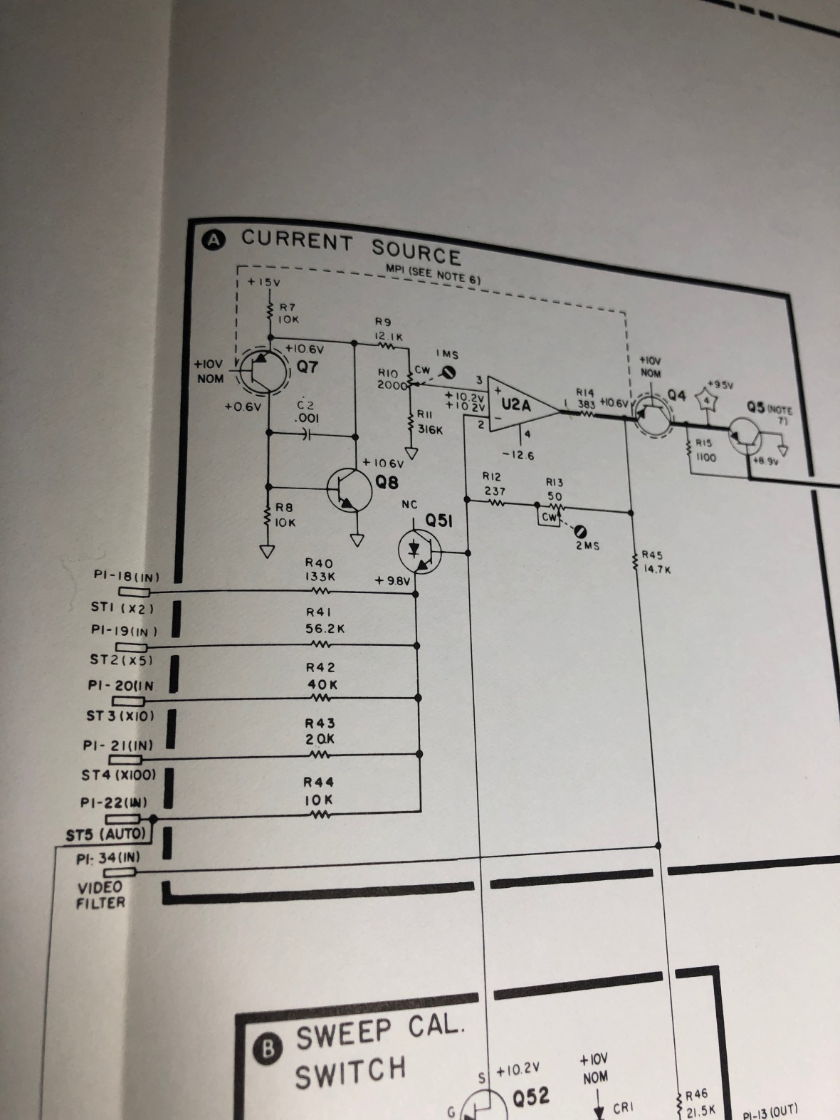
Schematic is really helpful, as they record bias voltages like Tektronix
With external injected signal and DC bias voltage on the schematic, it didn’t take much time to find the first offender, Q10, which was dead. I removed both Q5 and Q10.
Note:Even if the bias voltages are not recorded in the schematic, you can calculate the emitter to base voltages required for the correct bias, and approximate expected collector level. Same for tubes too, where you can confirm the grid/cathode is properly biased. Additional injected input signal can make it easy to find the faulty section of the circuit.
So Q5 was good, Q10 was dead. Here are the physical remains, One junction (B-E) is dead, B-C is good.
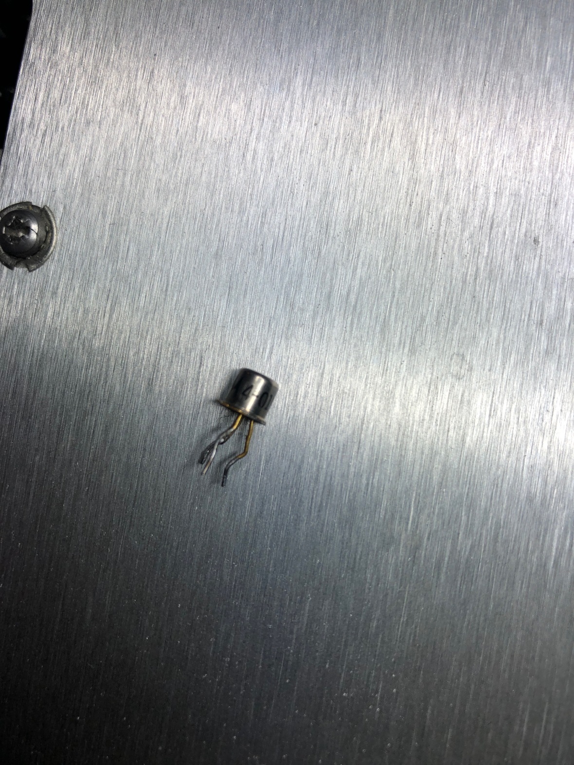
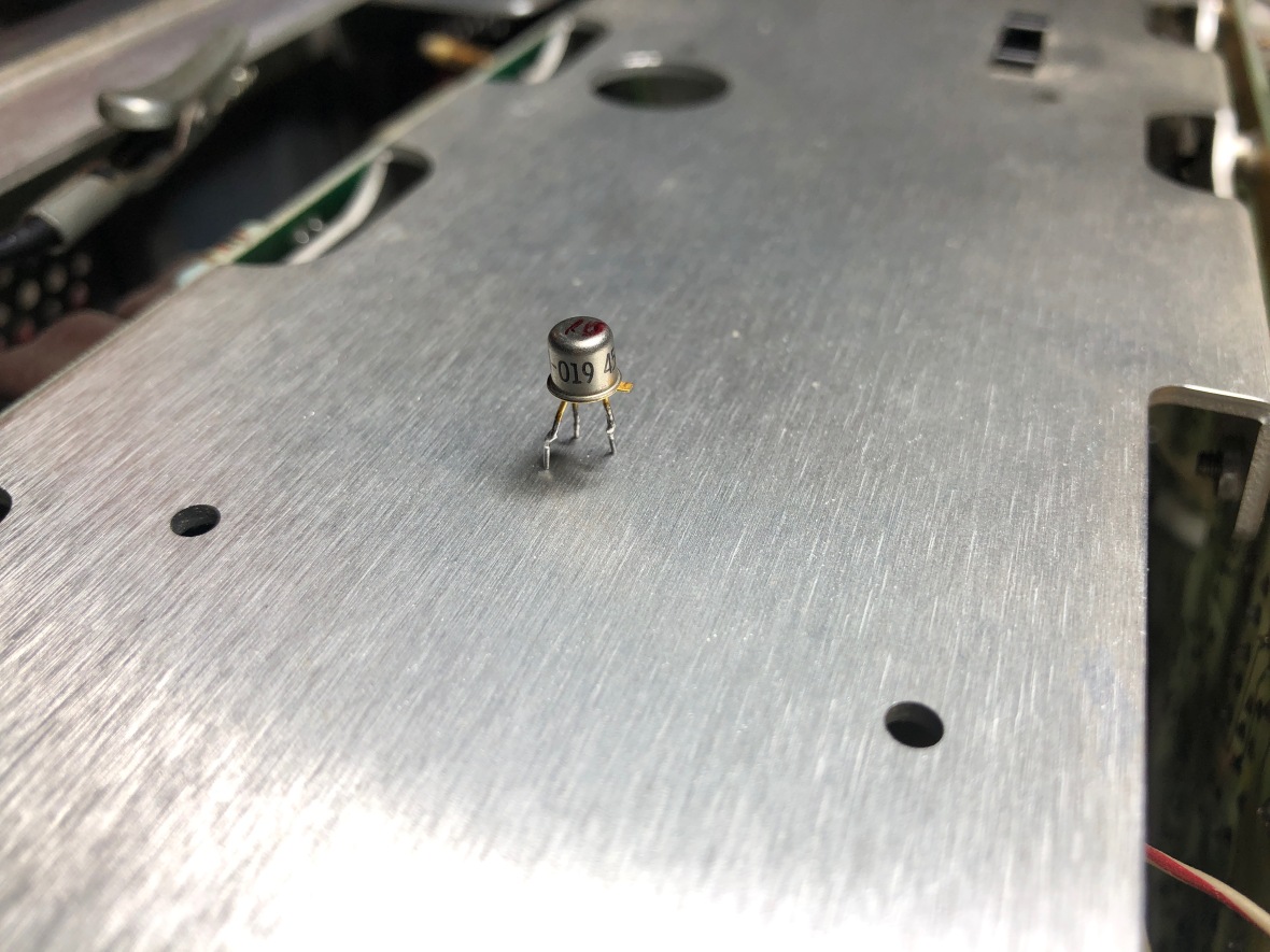
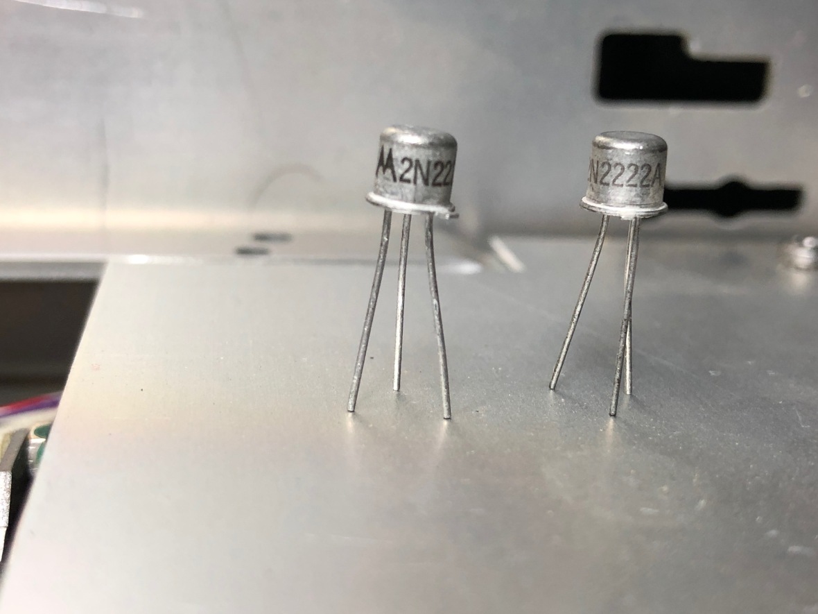
Now welcome to the world of HP, Q10 part# is 1854-0019, no trace of the actual transistor number anywhere. However some service manual changes for other instruments describe changing 1854-0019 to 1854-0477, which is a 2N2222A. Basically I could even use a 2N3904 as it is a small signal amp, with a maximum freq of ~200-300Mhz. To keep the signal symmetry of the origin’s design, I decided to change both Q5 and Q10, as there is a drastic difference in β from 2N2222 to 1854-0019. (2N2222 is ~200 where 1854-0019 ~70, figured this out from the working Q5)
I had only 2 X 2N2222 in my collection, so used both.
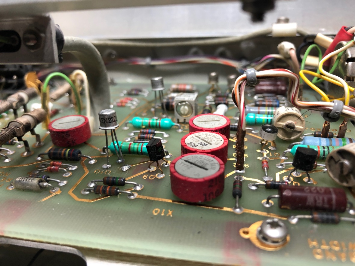
Here is the view after installation, I left the leads un-clipped. Yes – oscillation, lead inductance, radiation, weapons of mass destruction, all can happen here due to that.
Now it’s time to test – Powered it up with external H signal and here is the trace –
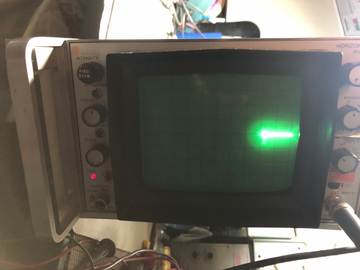
Not much improvement, but the good news was – I did see a proper biasing voltage on Q5 and Q10, as well as Q11 and Q6, which was the next stage – which meant that there was some improvement.
Now it was time to track both the push and pull stages. There is an easy way to find which stage, or if both, are faulty –
Inject a external H signal, unplug both H plate connectors from CRT, then plug connector one at a time and see which one is pulling the beam off the screen. The connector which pulls the beam is the working side and the one which is not causing much deflection is the dead side. As expected, here it was the top side, which is Q10-Q11-Q12-Q13 path which was broken.
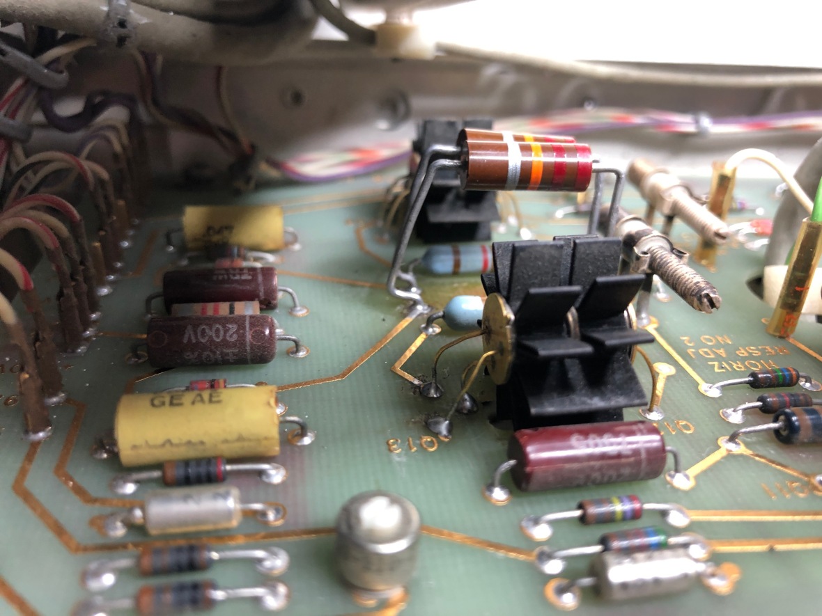
The easy way to check final stage is to keep the position control in the middle and check the deflection plate output from both sections (push/pull). Without any input, both deflection outputs should have same DC voltage to keep the beam in center. Here the top section had 4V output, from the expected +47V. The failed component here was the bias resistors for the final drive transistor. You can see them lifted up from the PCB in the picture – R29 and R53.
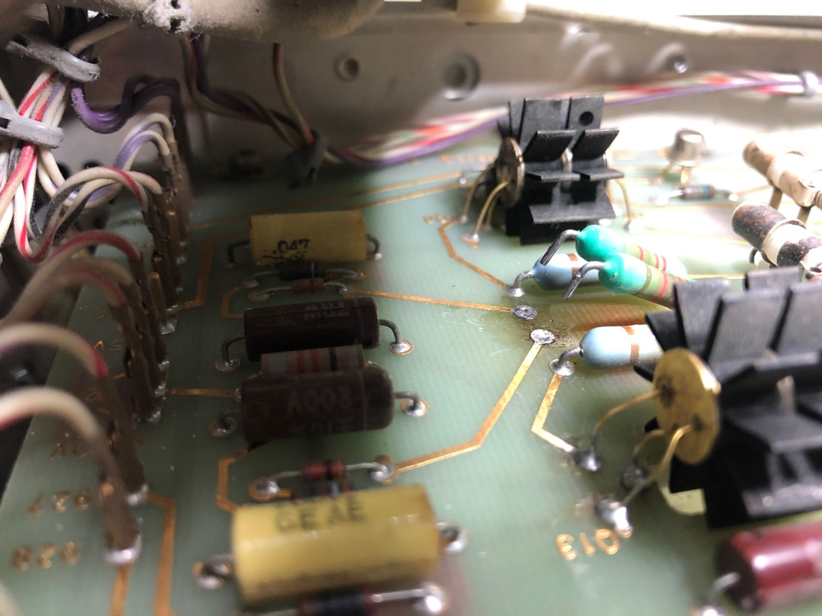
Here is the surprise, for the failed path, the 22.1KΩ resistor was open. for the bottom rail, it was 37KΩ. So the lower section of the push/pull was working but with lower gain.
So now I have a bigger hunch of what happened. Since the Q10 failed, there was no AC signal coupled to the base of Q13, which eventually fried the R53, which then killed the bias to the final drive transistor Q13. Wonder why they didn’t consider this in the design and adjusted the component values (power rating) accordingly. Second part is keeping these resistors close to PCB and burning board out. They are expected to get hot, would have been ideal to lift them up a bit from the board, but there will be signal integrity issues in consideration here?
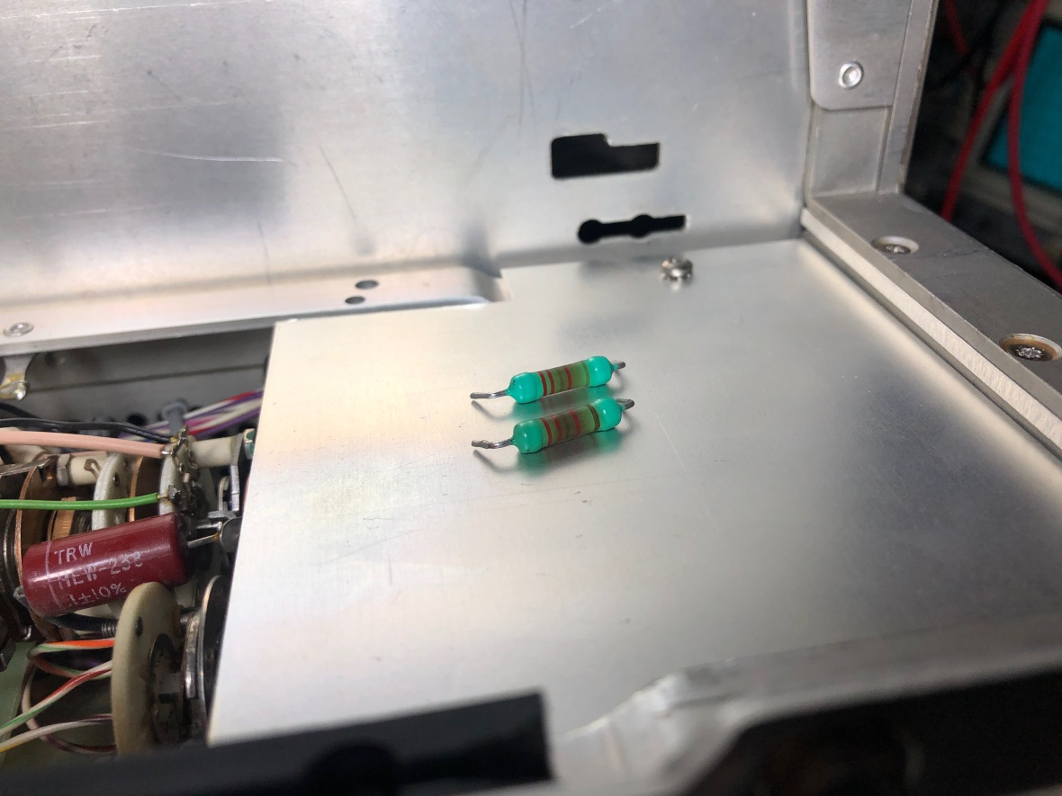
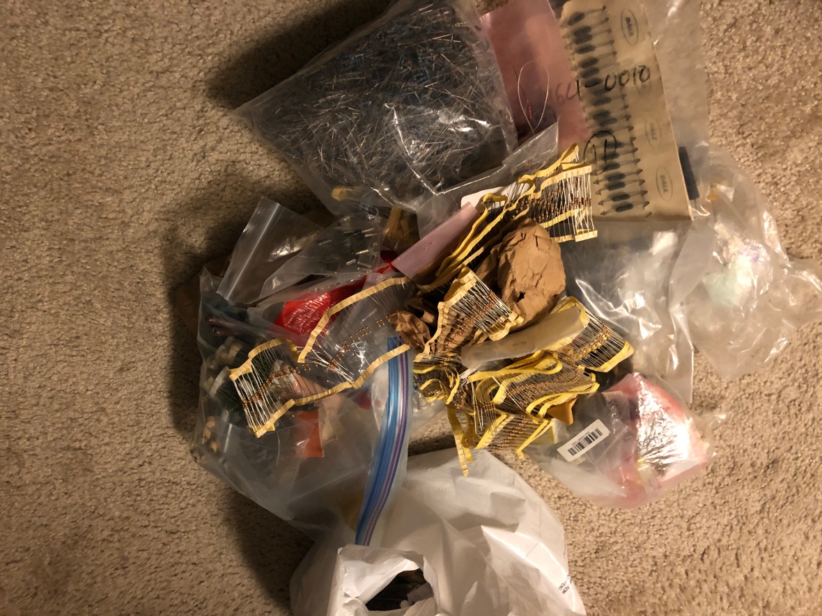
It’s time again to pray to the HP part gods. Both these are 22.1KΩ, 1/2 W, 1% metal film 🙂 . I had no choice other than to rummage through a sack full of resistors to find two matching 22KΩ.
Exactly after 32 minutes, I was able to find two 22KΩ, matched on my HP 34401 to the closest value possible. I upgraded the power range of these resistor from 1/2W to 1W.
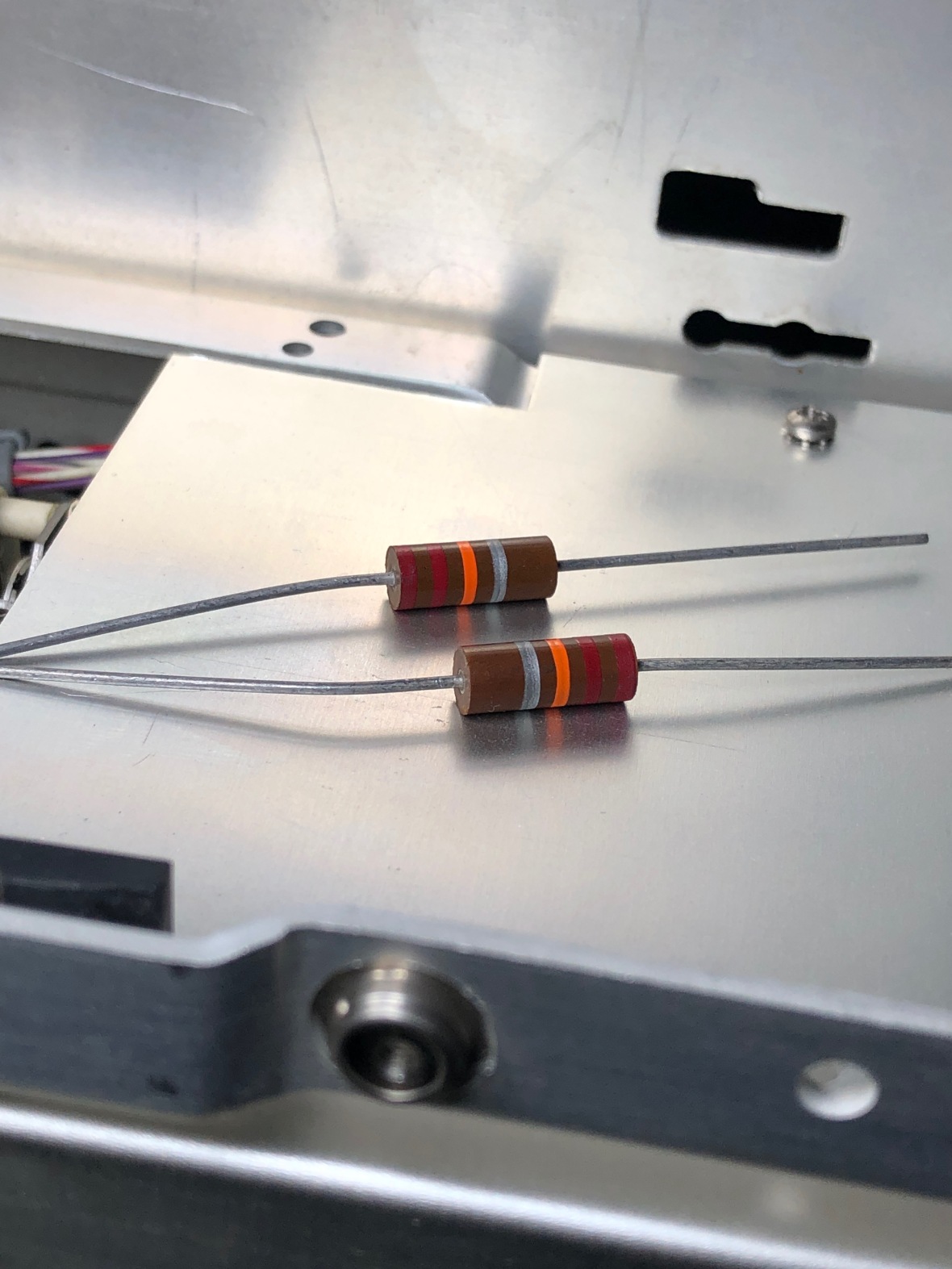
These are carbon composition, rather than metal film. It could burn out, if overloaded.
Here is the final install to the board, as always lifted them up to avoid burning the PCB.
And here we go – we see the full trace, H-Position control working and the main frame back in order.
Now it is time to start looking in to the spectrum analyzer plug-in –
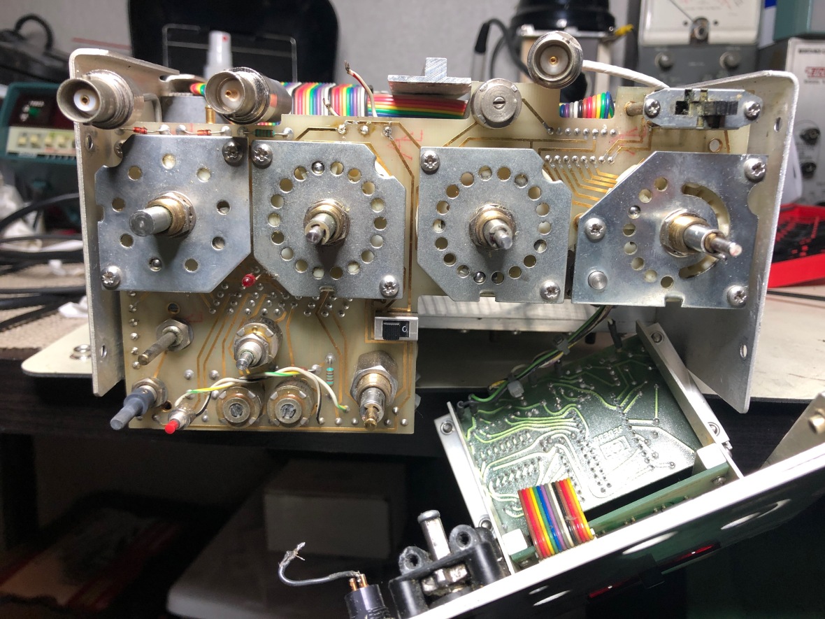
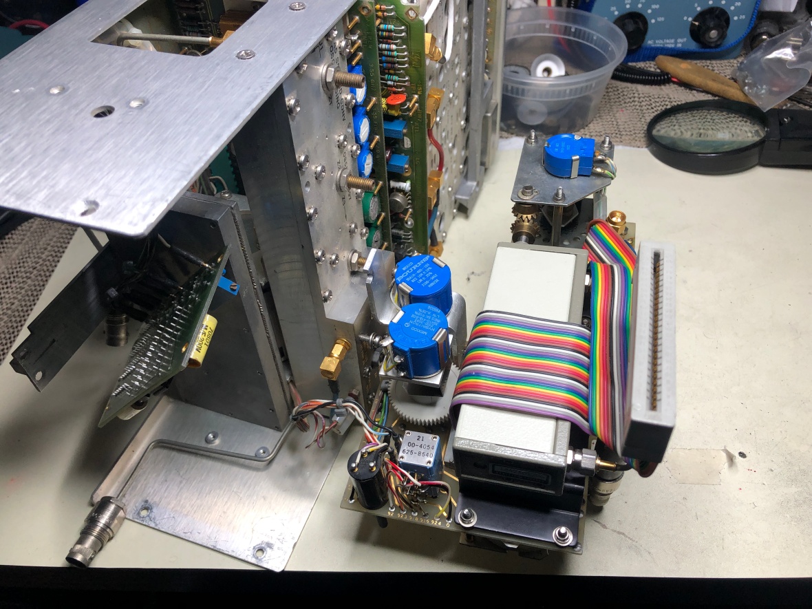
Here is the unit, typical HP design, with PCBs on slots. Very hard to troubleshoot without raiser cards and extension cables.
Top view, I have removed the A8, sweep generator card for inspection.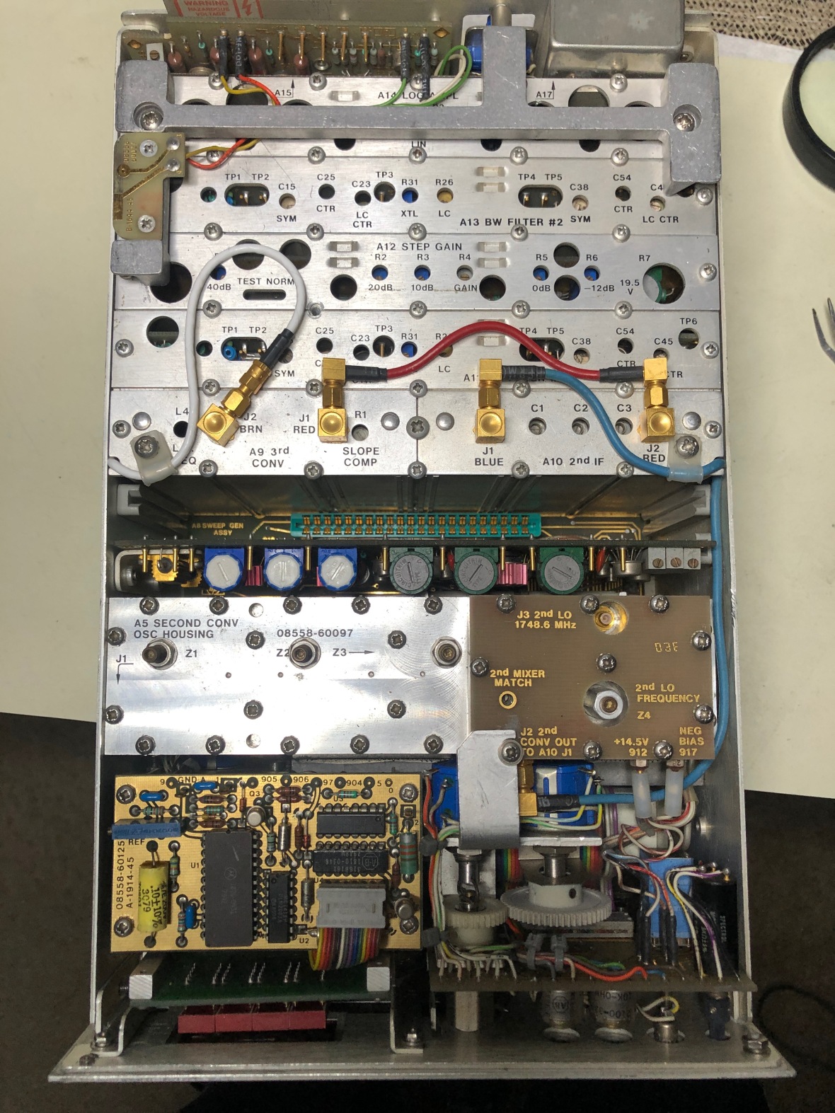
Here it is with A8 in.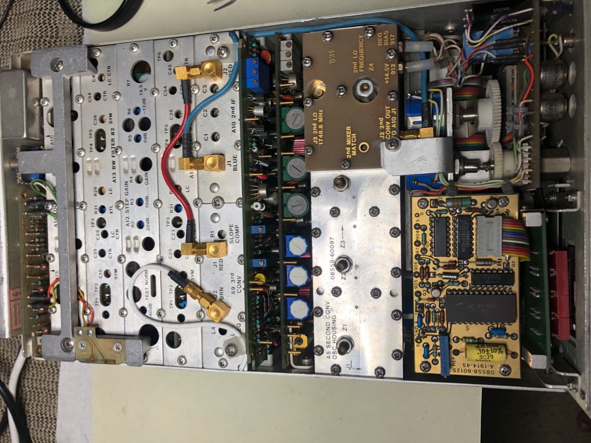
Front Panel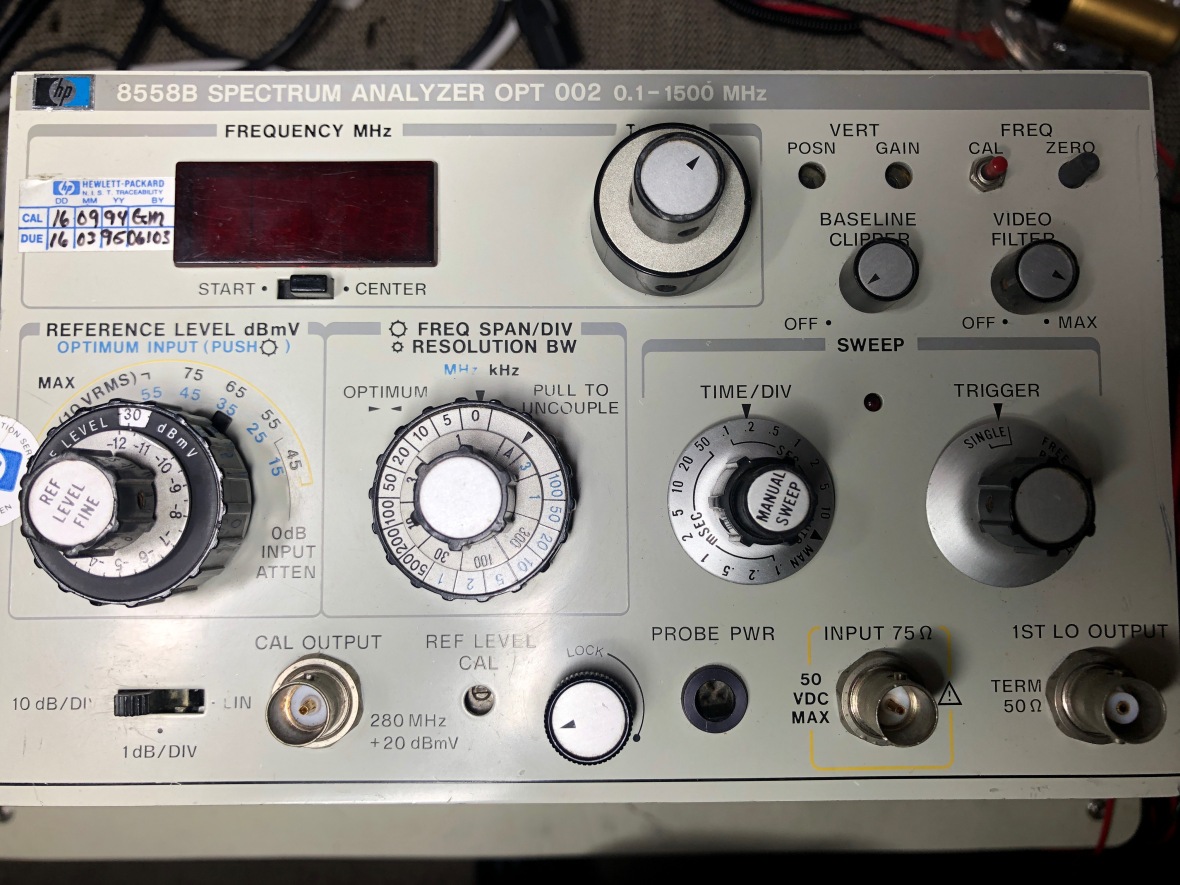
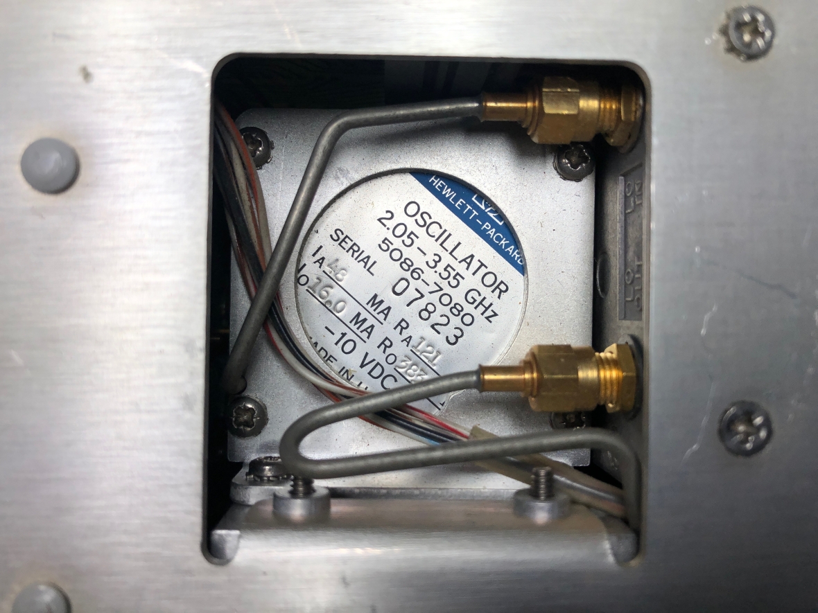
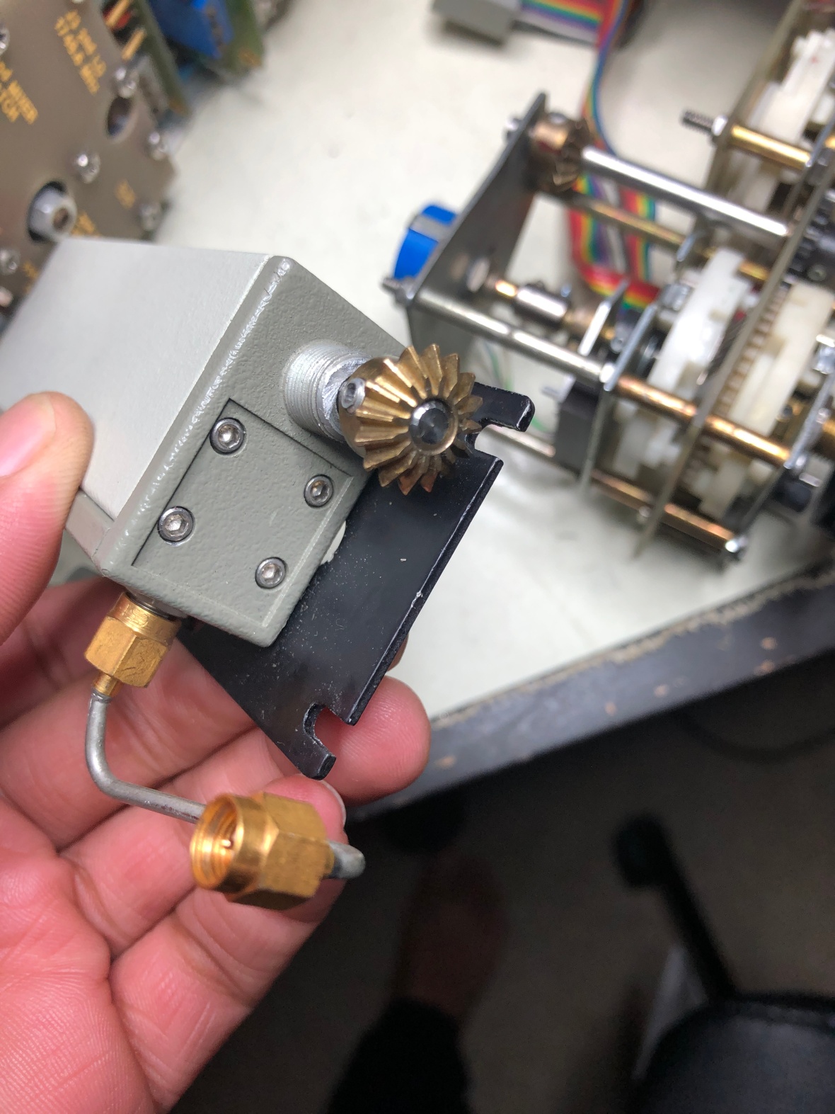
The YIG
And the sweep is generated by A8 card. Pulled it out for inspection as the trouble was no sweep.
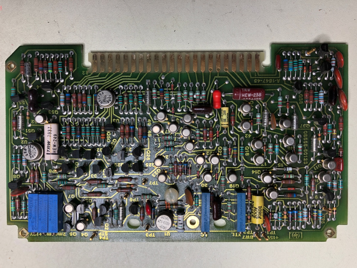
Looks all clean, unless an active component like a transistor or op-amp failed.
It is a standard RC Sweep generator, what can go wrong other than op-amp ?
Continuing visual inspection,
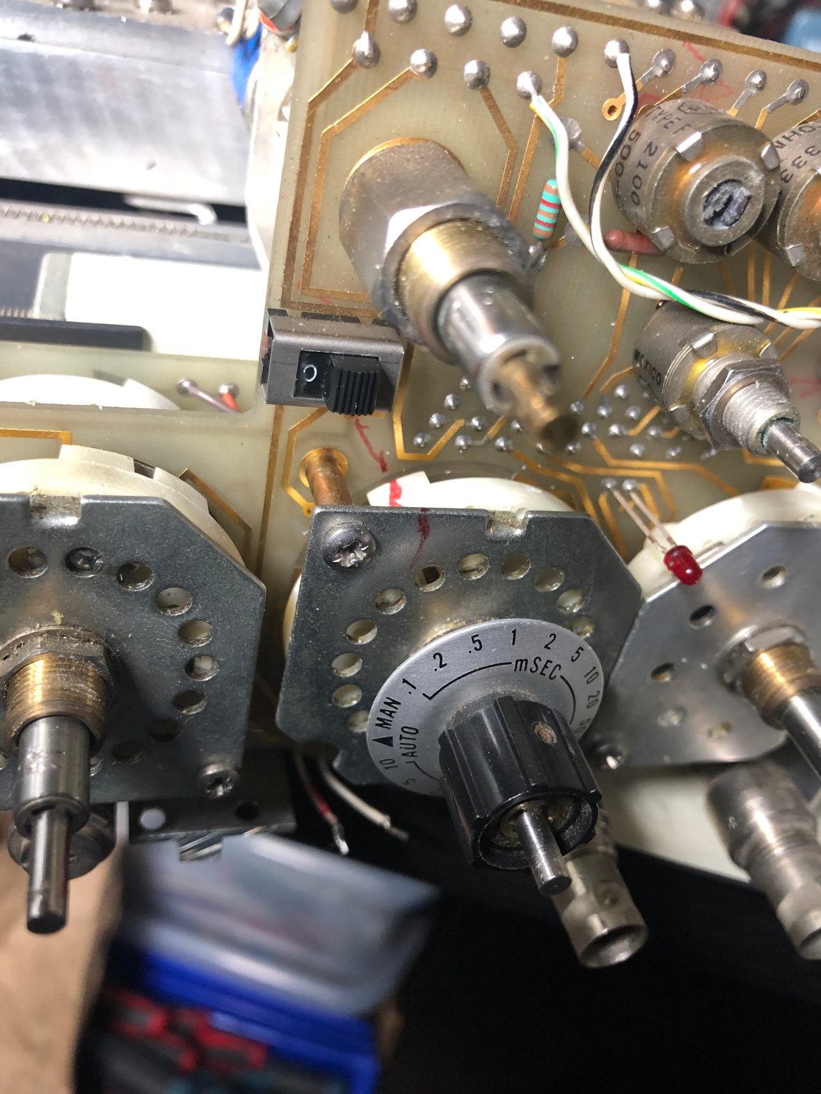
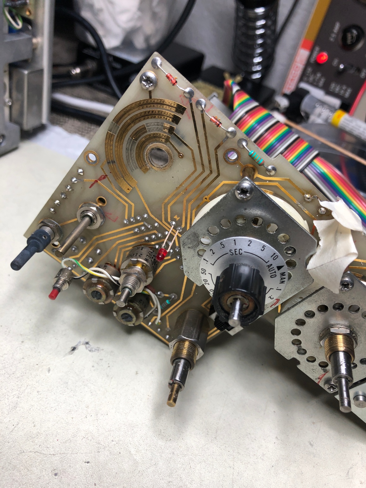
Front Panel and switches, looking for dirty contacts. Very tight and complex assembly. PCB traces as switch contacts.
Well, rewinding.. interesting, here is the time base switch
And here is another switch from front panel.
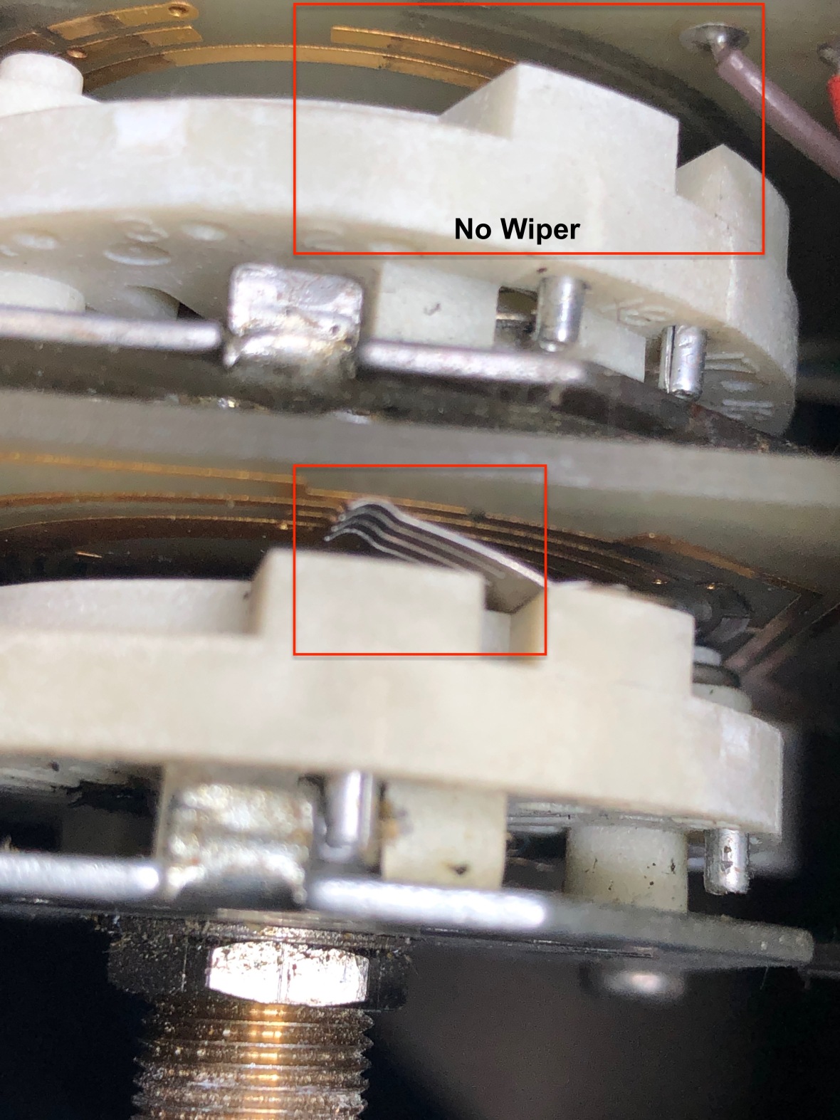
Here is the switching wiper on other switches,
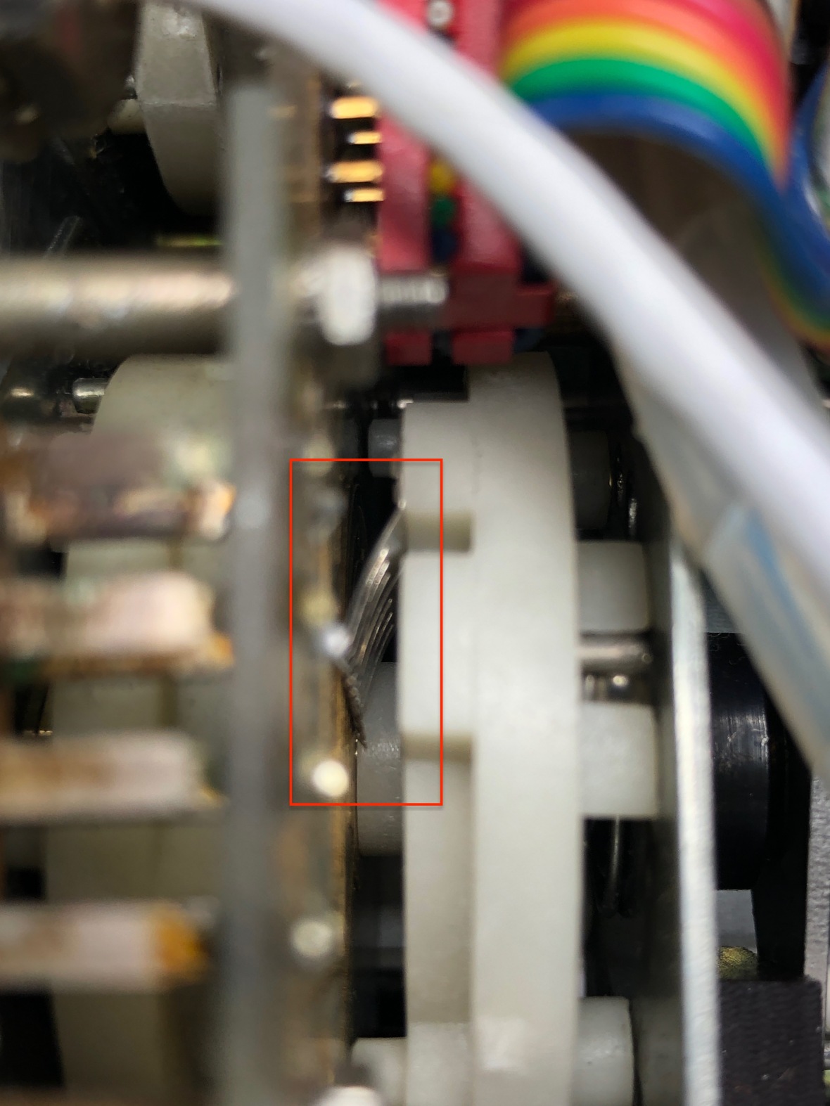
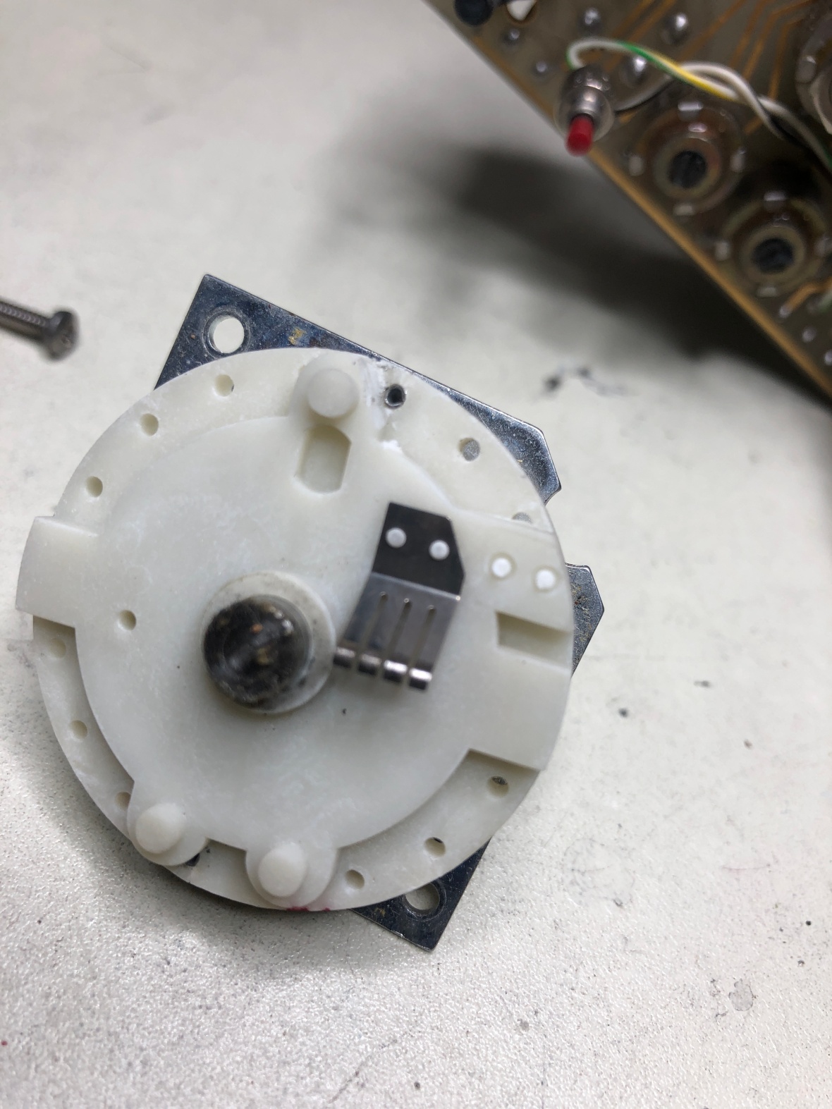
and here is the time base switch again – where the switch contact is missing.
So timebase and sweep will not work. That gives me clue to the UFO I found inside the chassis. It was the remains of one of the switch wipers.
Since I have come this far, I decided to see how bad the switches are and decided to remove the front panel to access the switches.
And the knobs. 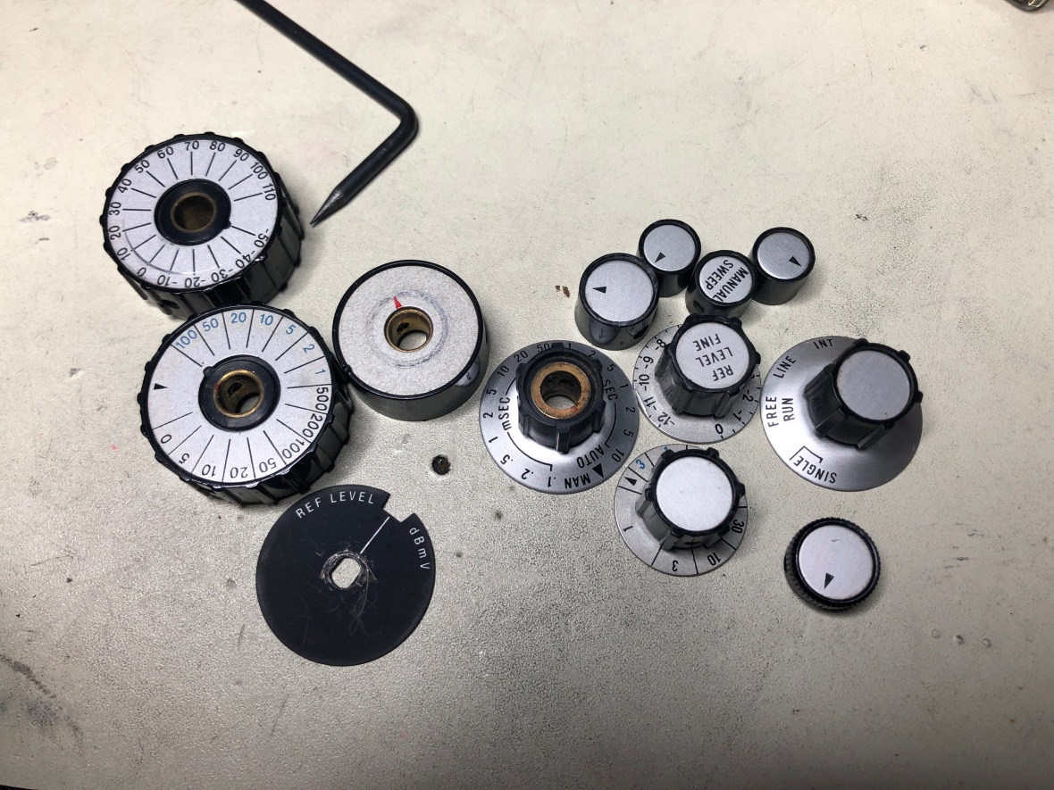
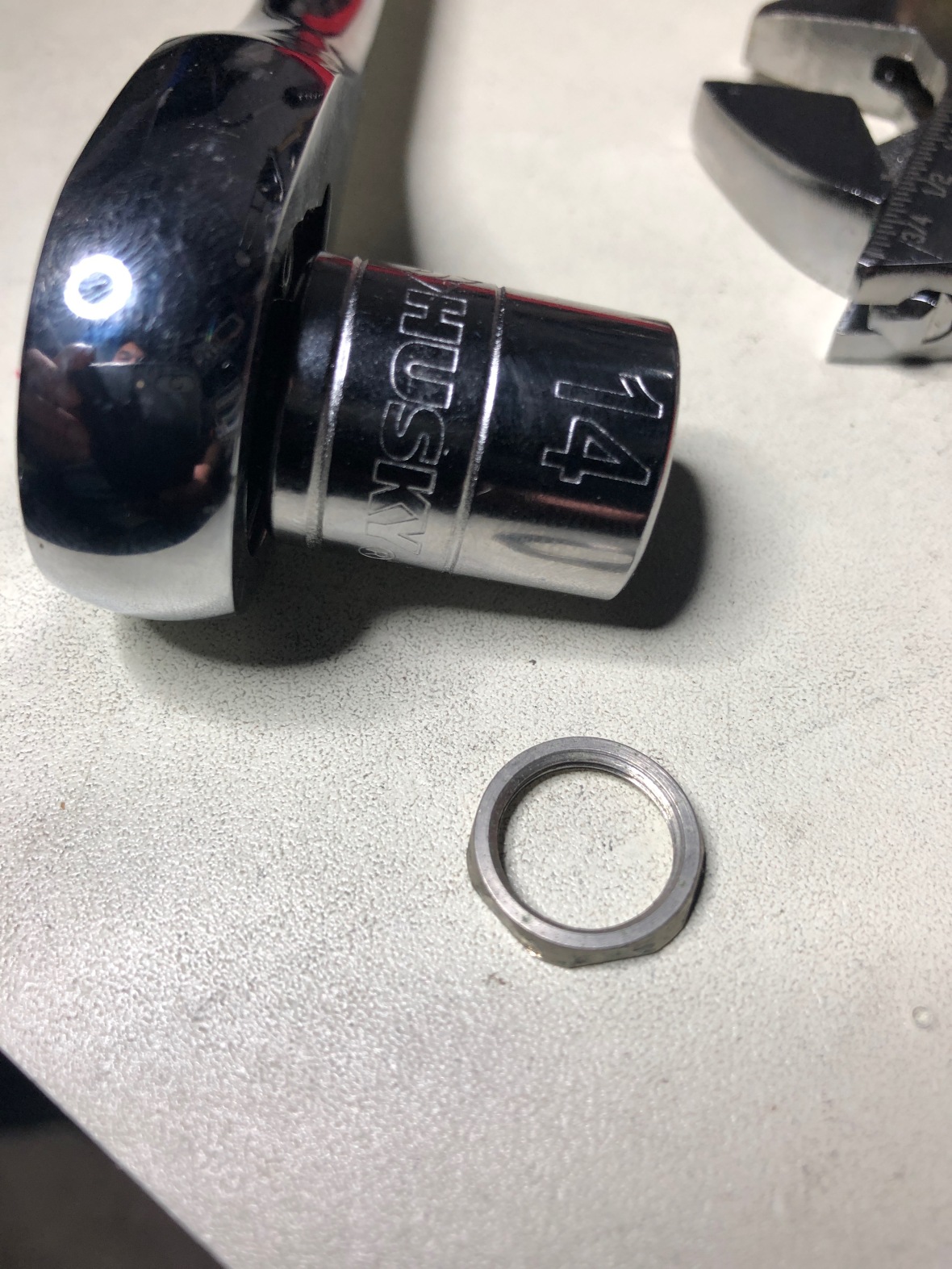
Then you need to remove the co-ax connectors and probe power cables. Had to use a 14mm socket to remove the weird nut around co-ax.
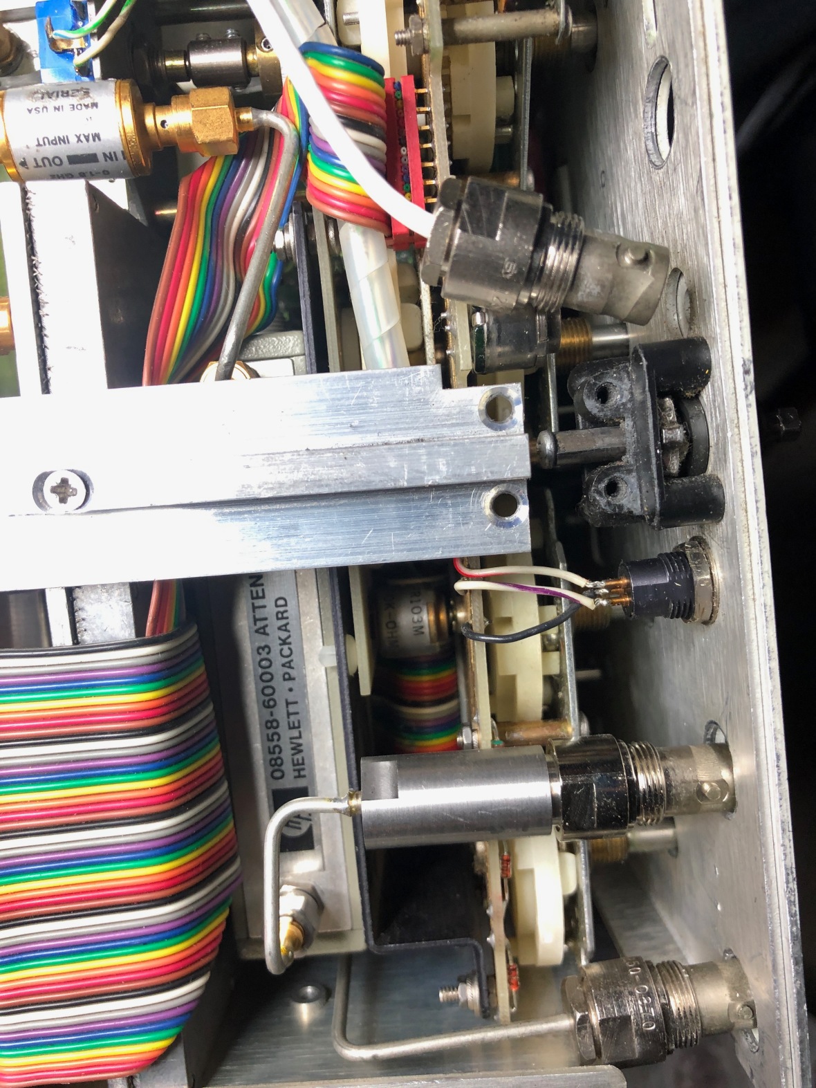
Here are the co-ax off from panel. Do take care of the rigid co-ax connectors.
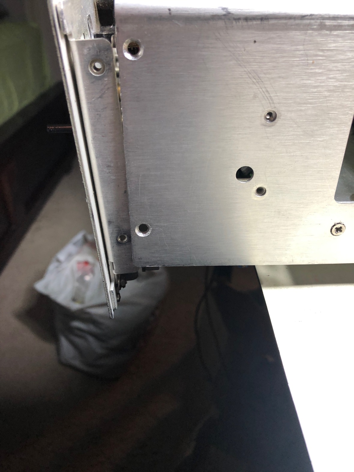
Then the undo the screws holding the panel.
And here is it. I removed the digital display panel PCB Board off as I didn’t want to disconnect the cables.
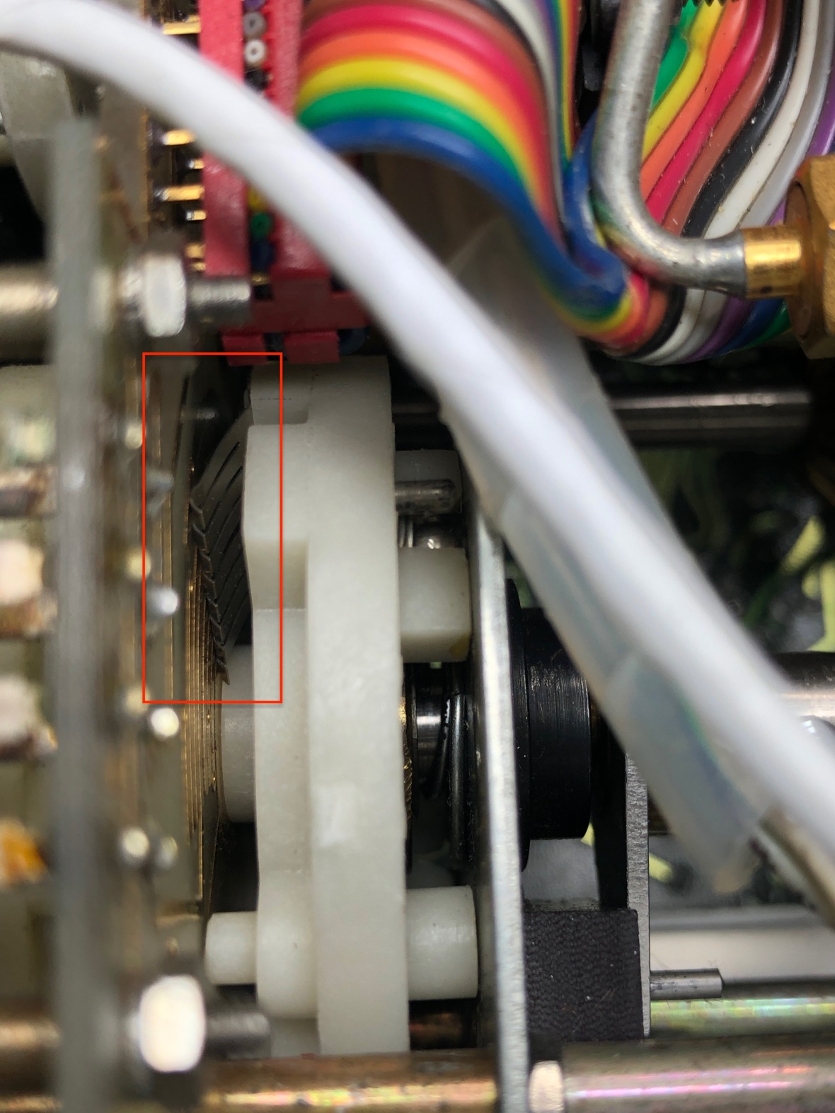
and its not the timebase switch alone which is faulty, but the video resolution bandwidth switch is also missing the contact wiper – 😦
Decided to open switch up in the hope of finding the wiper hanging in there, but was not lucky.
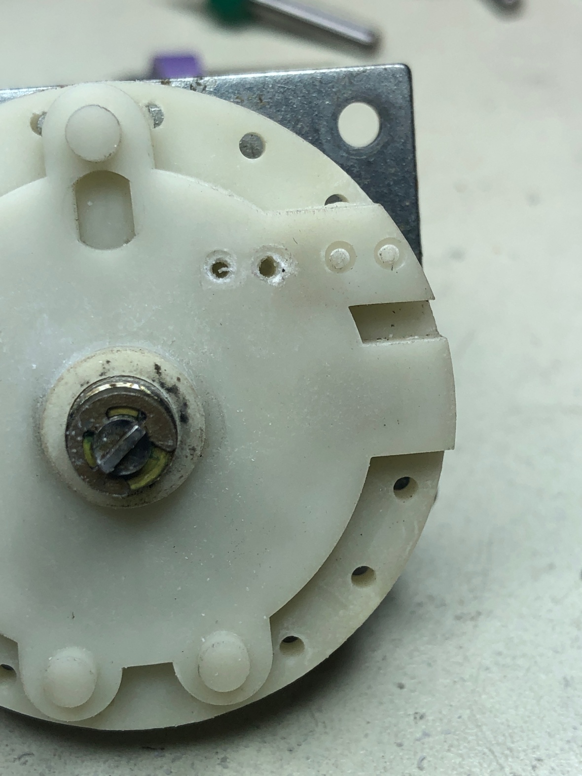
Here is the timebase switch with no contacts to make any connections
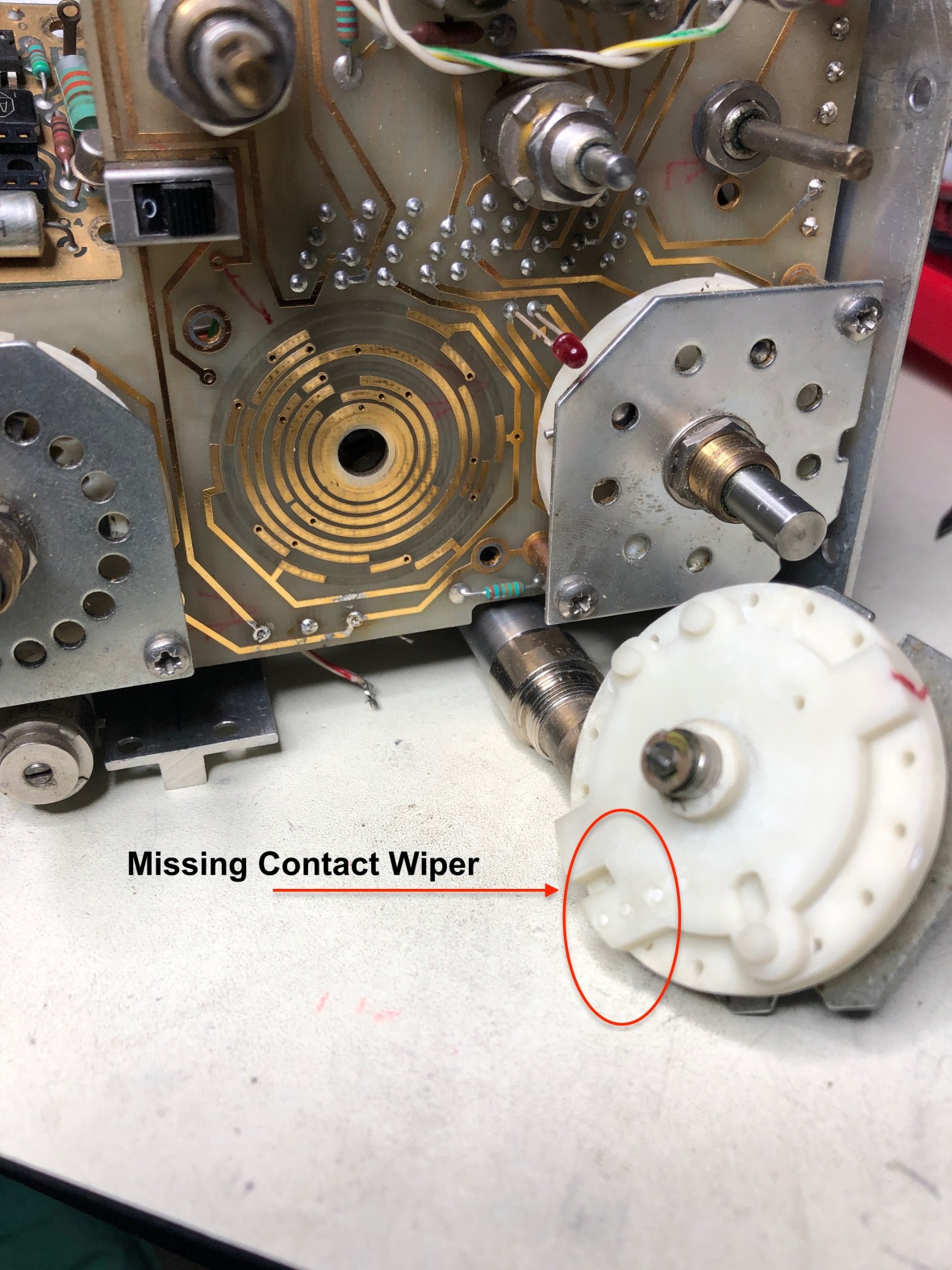
The plastic riveting or soldering whatever so called, holding the wiper contacts break off, causing the whole switch to fail. This switch needs two wipers with 4 contact arms each.
Almost looks like end of the road for this unit, unless I can find a spare unit with good switches.
A google search around spare switch showed this plague affecting several HP instruments of that era..
… To be continued …if I ever get a spare unit or switch.
1/24/19-
The contact wiper image was shining in my head all the time and while searching for something in our store @at work, an old hard drive removed from a NetApp storage array caught my attention –
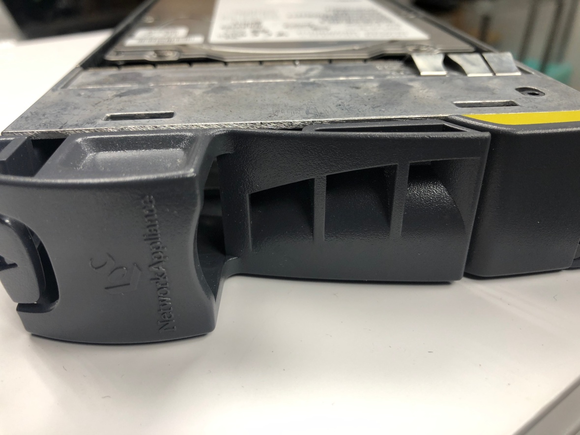
Up closer 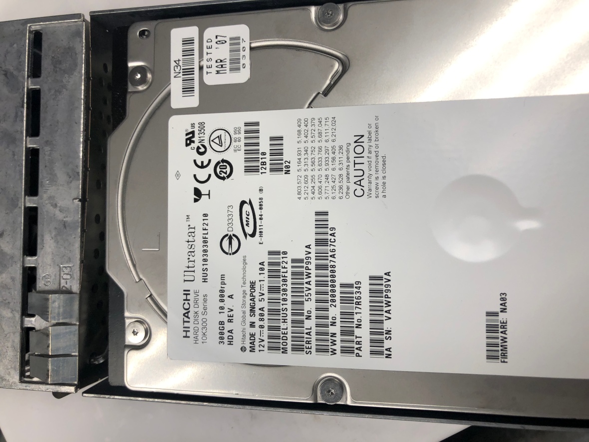
and up closer, here is what I need. 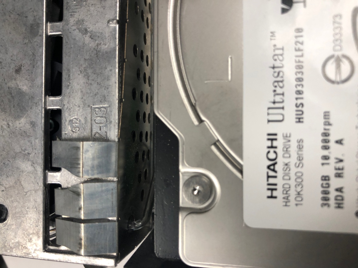
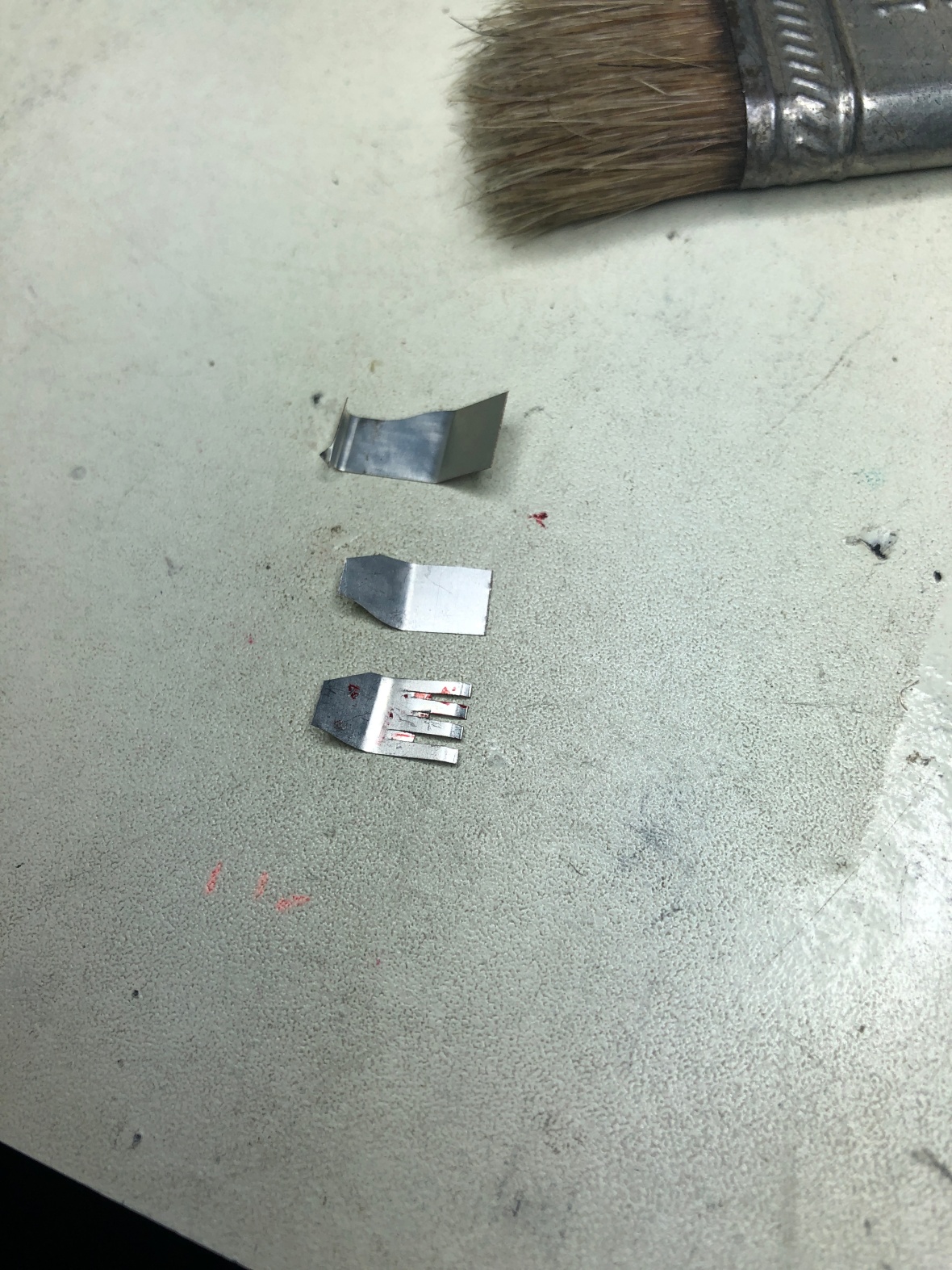
And here it is being transformed in to the part needed.
{{ The fingers are not really needed, I could use it as it is, but better to have them to reduce the stress on PCB}}
Drilling holes with PCB drill and Dremel,
And Installation – I used only one screw as I had only few of these tiny little screws. 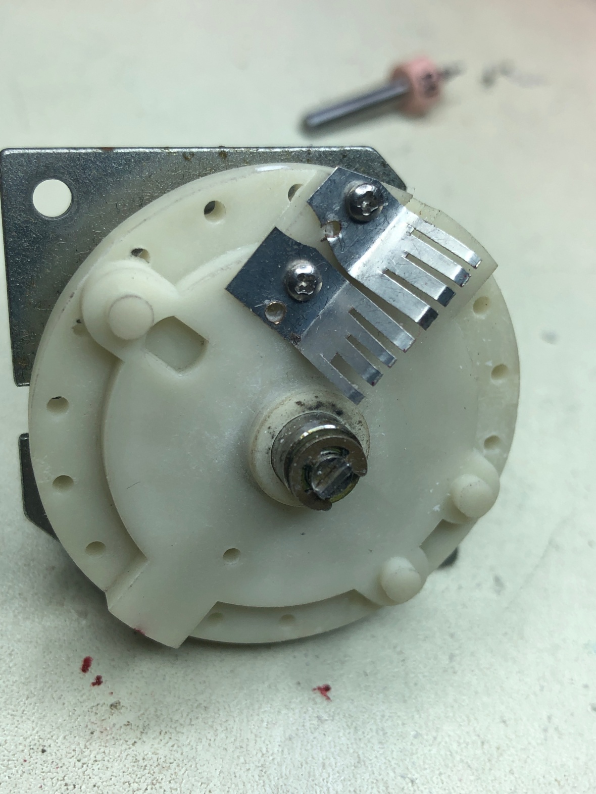
Reassembled the switch.
In to the mainframe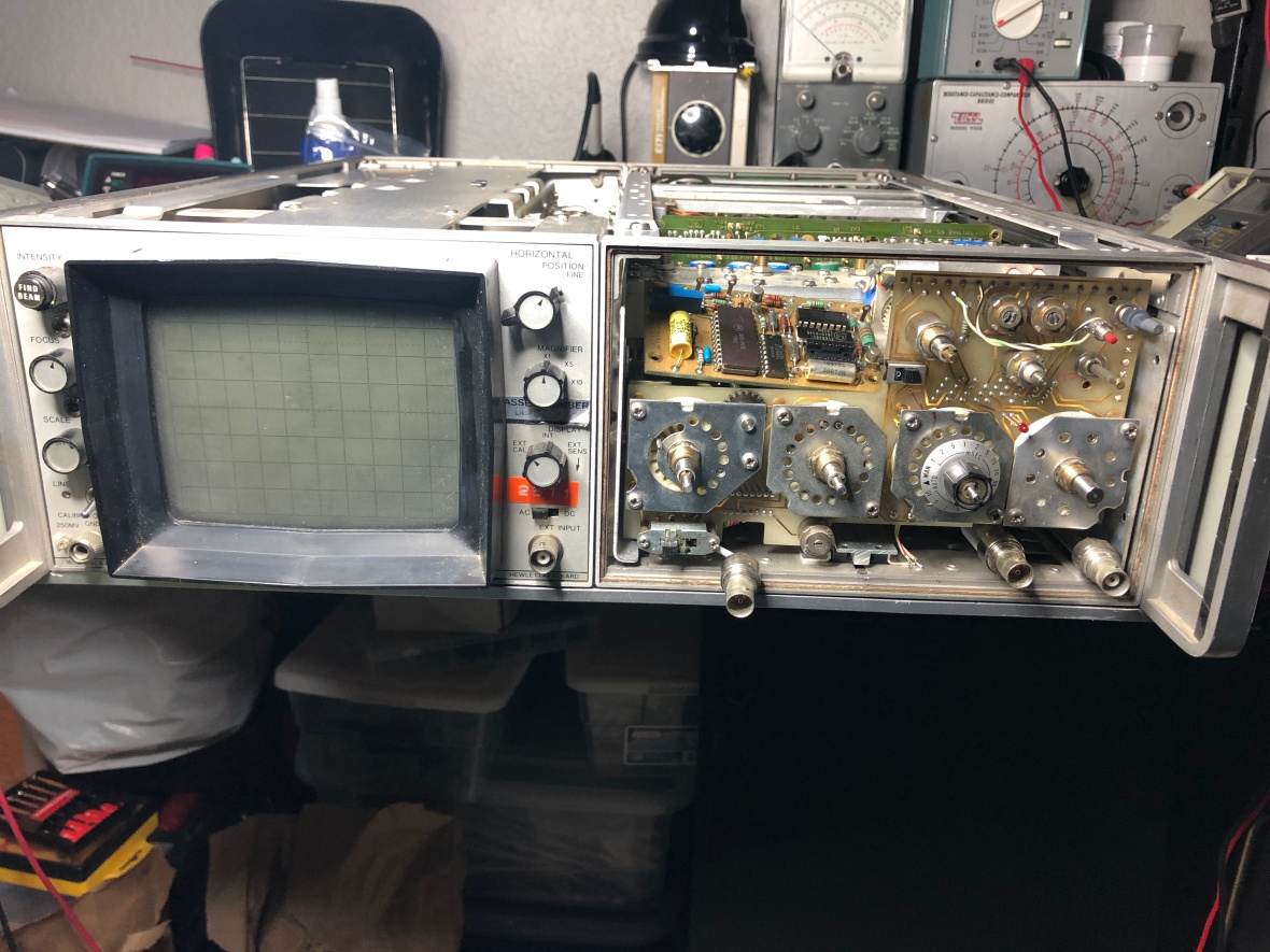
And here you go 🙂 , Time base IS working. All positions are working fine. 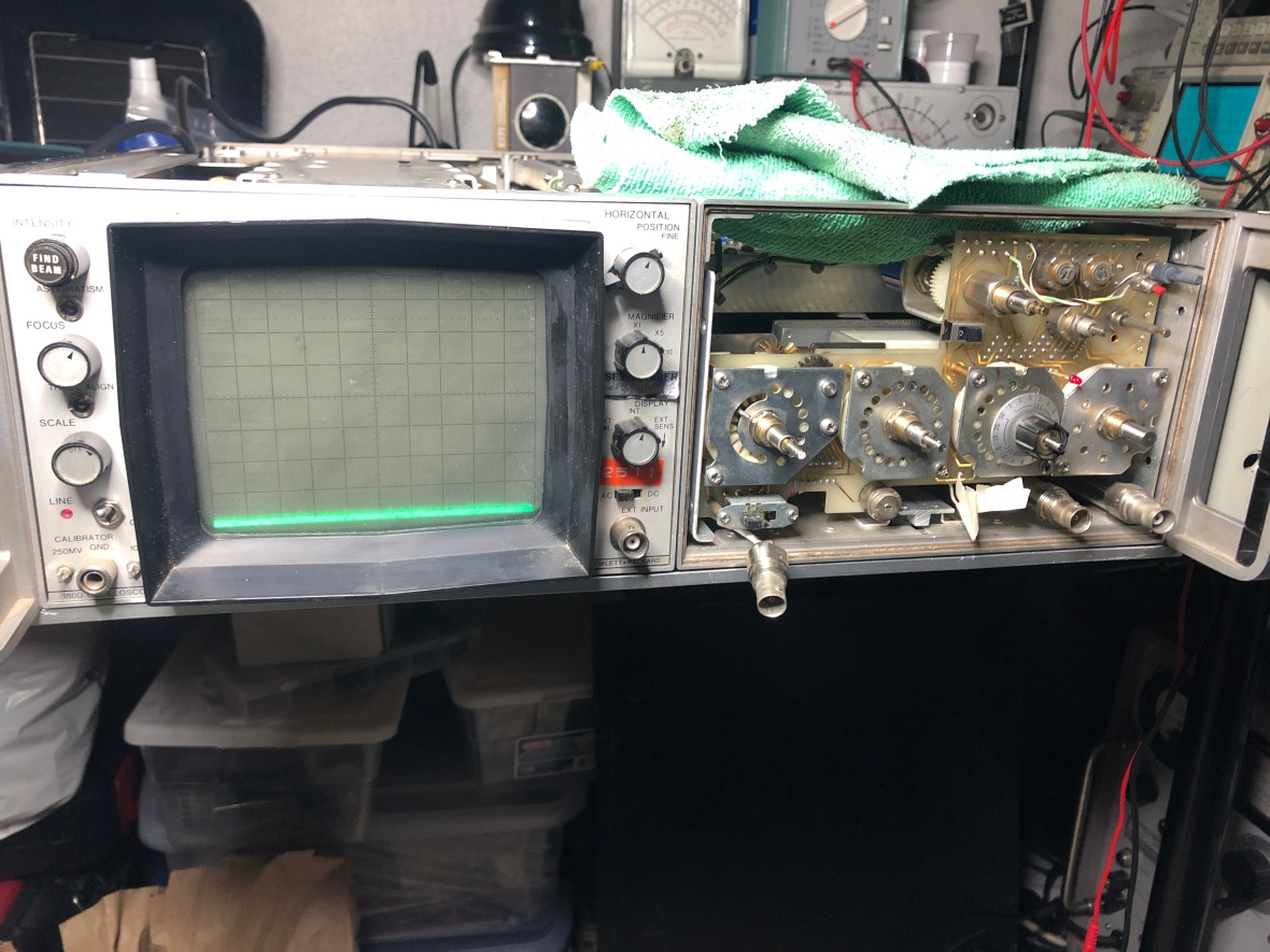
But, not much to celebrate. I did a detailed inspection of all the switches and all the switches are missing one or both of the contact wipers :(. In short every switch is broken.
Fixing one switch is an hour worth task, and removing the resolution bandwidth switch is even bigger trick as its stacked behind the main frequency/div switch.
Not sure if I am gonna chase this or not..Still thinking ..//
… To be continued based on unknown conditions ..
Update : 1/25/2019-
The main struggle of repairing the switches is in removing the main switch – the resolution bandwidth and frequency per div – -Combination switch is a real pain. I decided to give it a try and I was not ready to give up. So whole of friday night was dedicated to switch assembly,
WARNING : DO NOT ATTEMPT THIS UNLESS YOU HAVE ALL THE PATIENCE IN THE WORLD, WILL BE NICE IF YOU CAN BORROW BIT OF IT FROM EVERY PERSON YOU KNOW. THIS IS REAL PAIN.
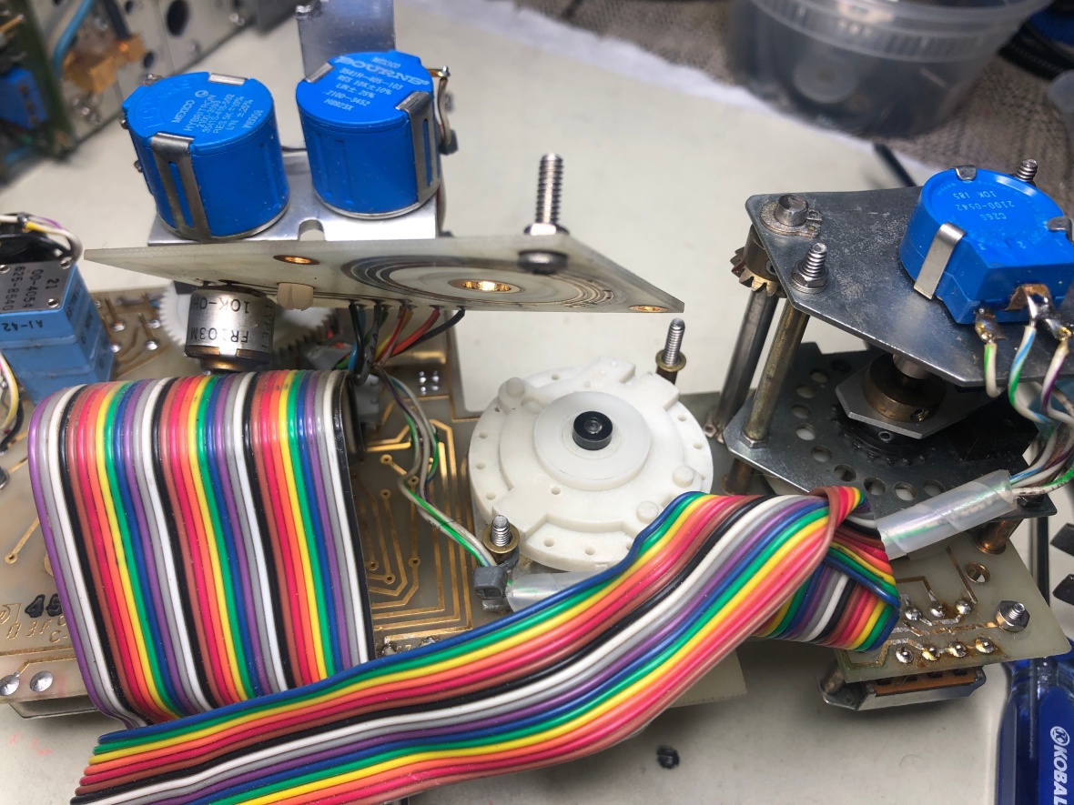
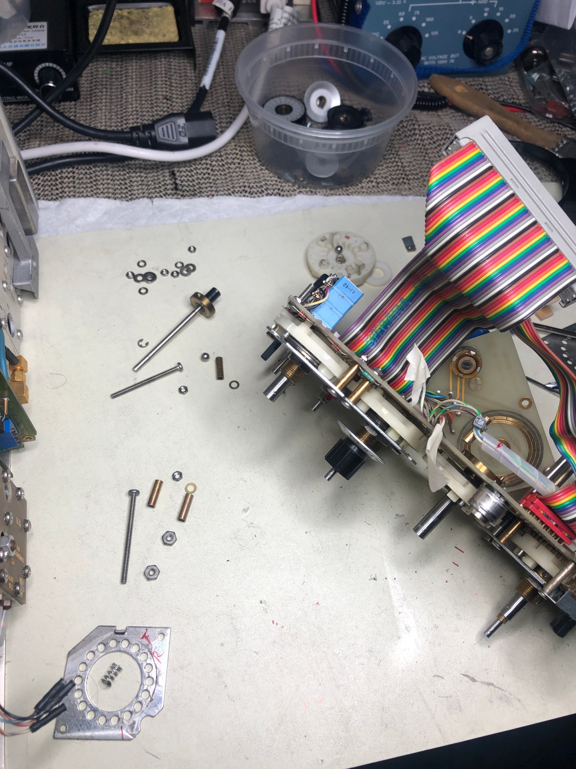
Now I have disassemble the plug-in front panel completely, and remove the entire switch assembly from front panel. Remember to disconnect the front end attenuator rigid coax.
Disconnect wiring to main PCB for Pots. 
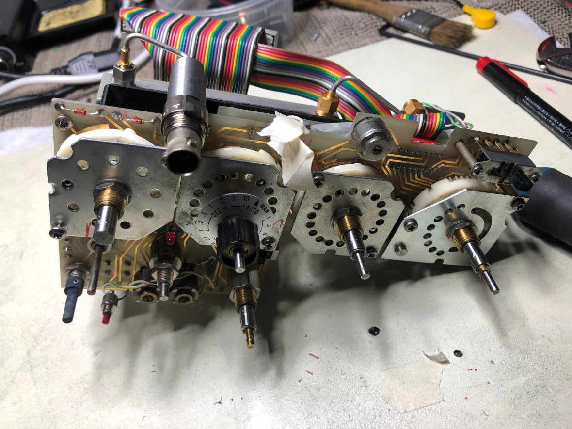
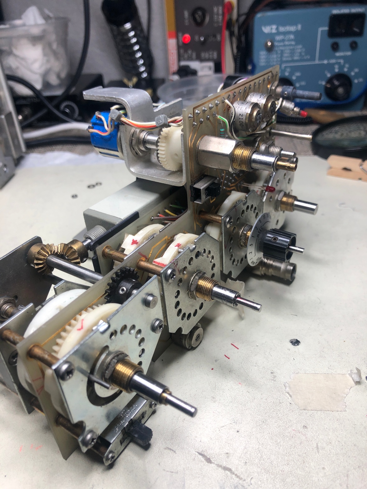
Here is the front panel switching assembly off the plug-in body.
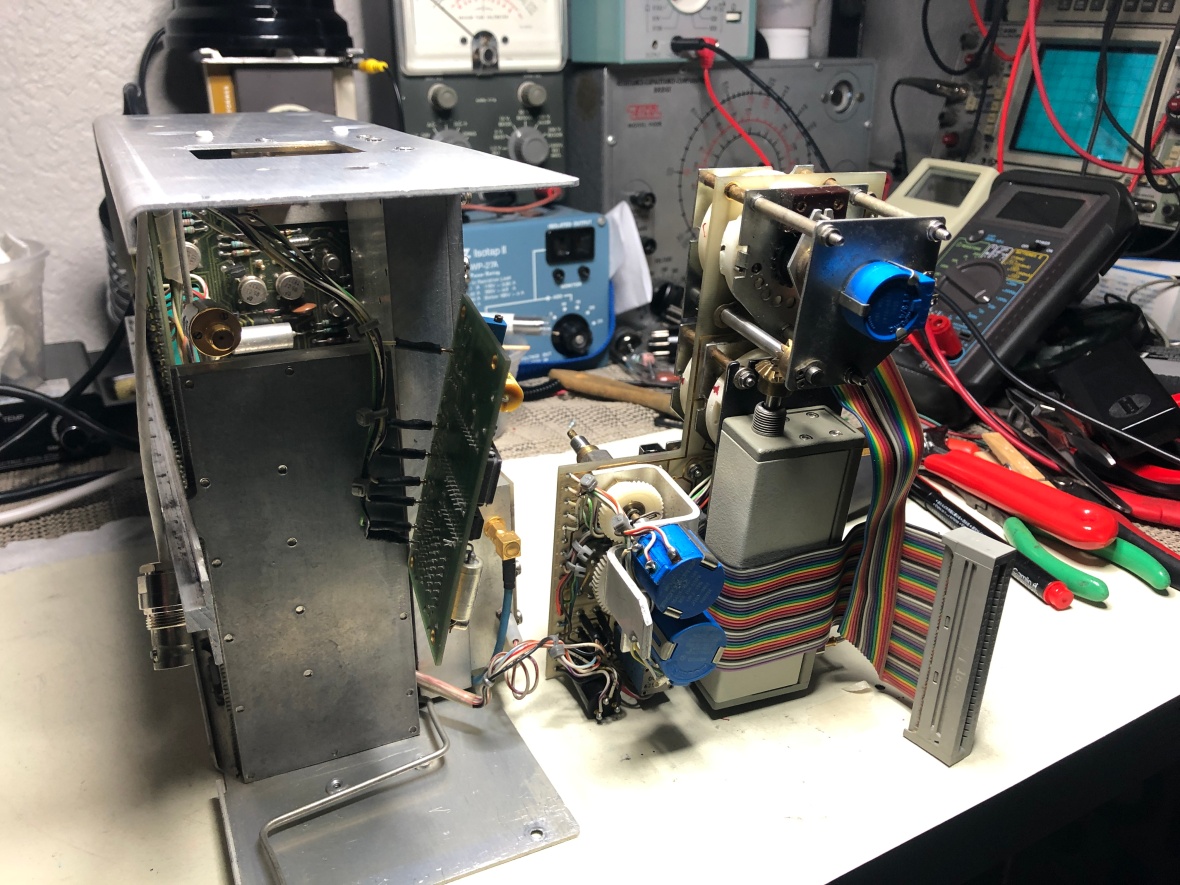
Here is it again, looks like a clock. All the switches are mounted in the worst possible manner that its impossible to remove just one part. But that is the fun in all this 🙂
I left the frequency display PC back in the plug-in body. Did not want to disconnect the cables.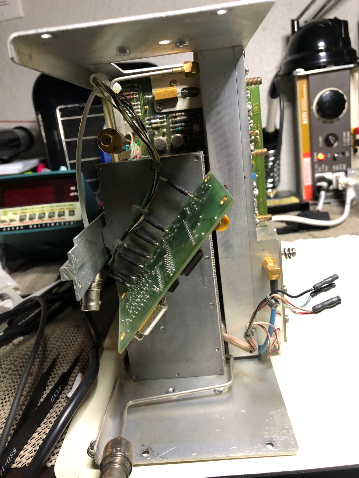
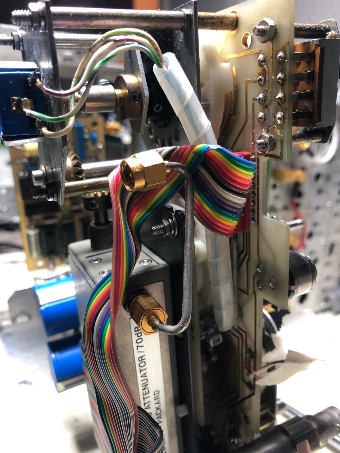
Here is the view from back, front end attenuator . You can see the gear drive to it from main panel. The marker you see down below is used to mark the position of every object in the front panel, to put it back together in right order. You will see red lines all over the assemblies, which is my way of tracking the position. 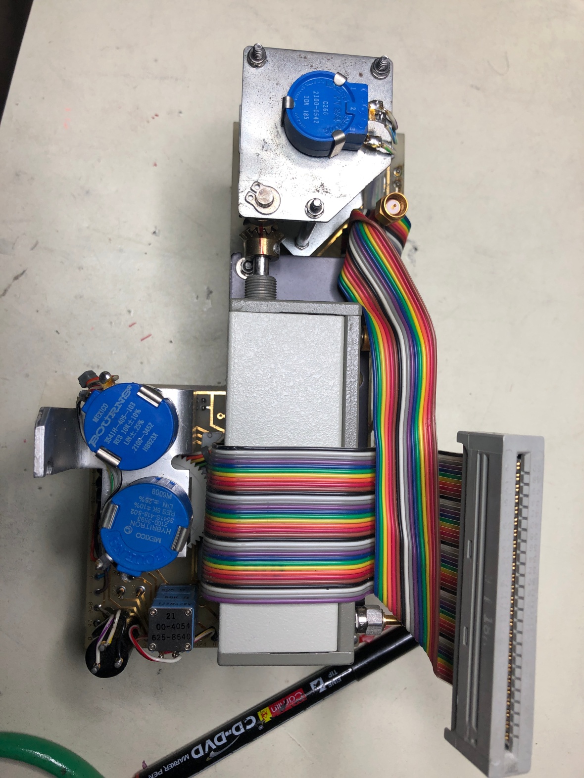
Anther view, showing you the input signal path directly to the attenuator. This is 75Ω version. 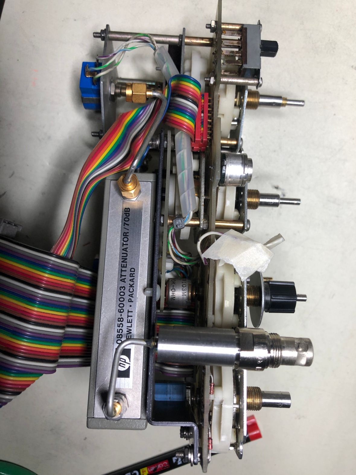
I have to remove and repair every switch. All the switches are missing either all or one out of two contact wipers. Removing the attenuator is the next step. 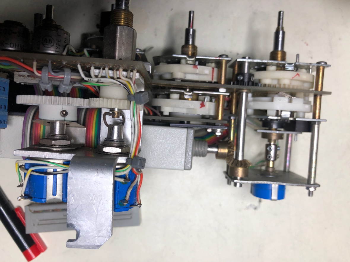
Mark the gear position for ease of reassembly. 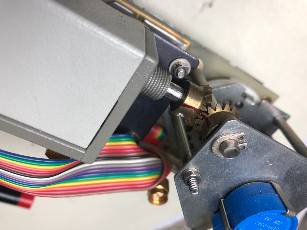
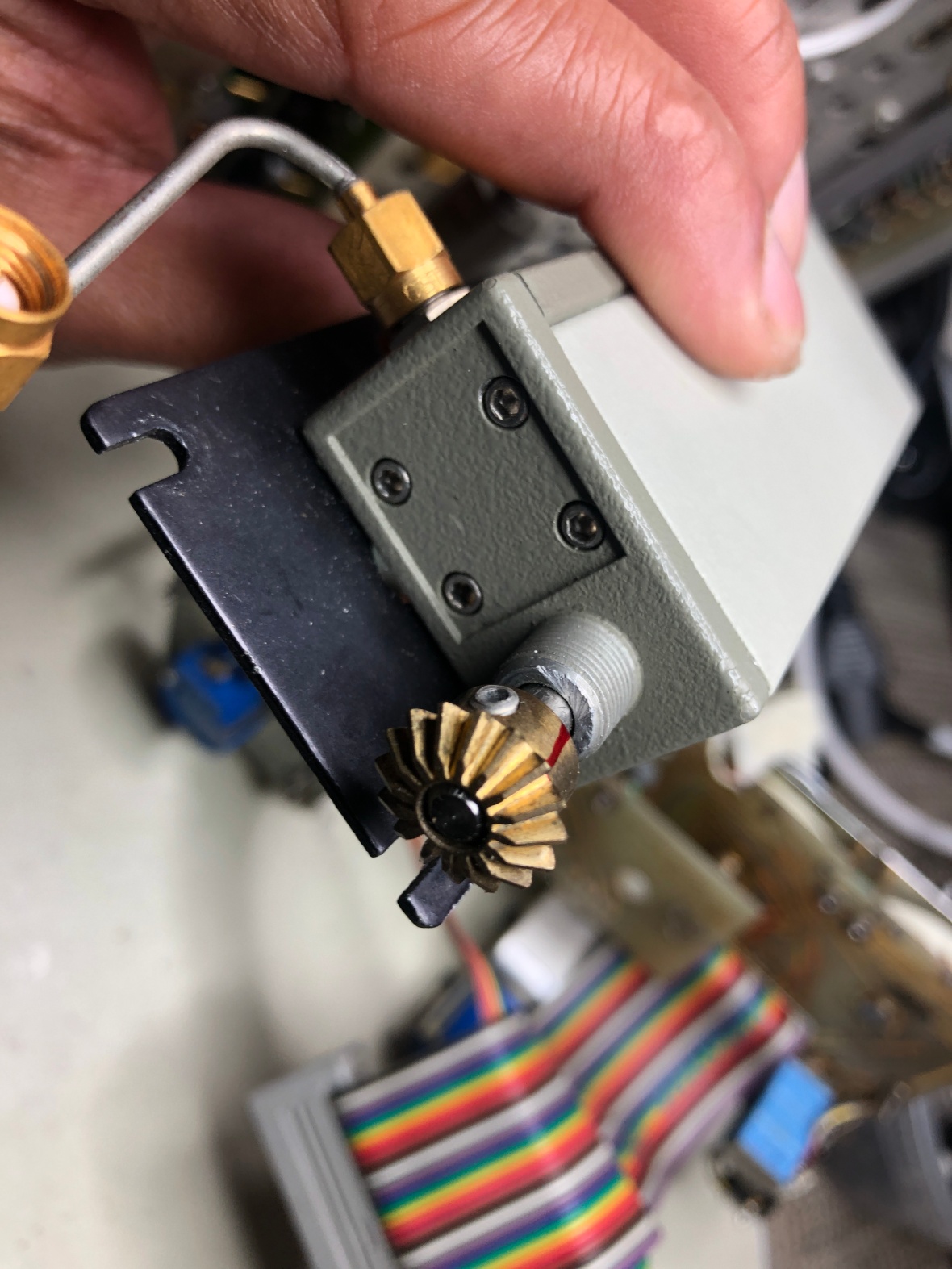
Here is the attenuator with mounting bracket. 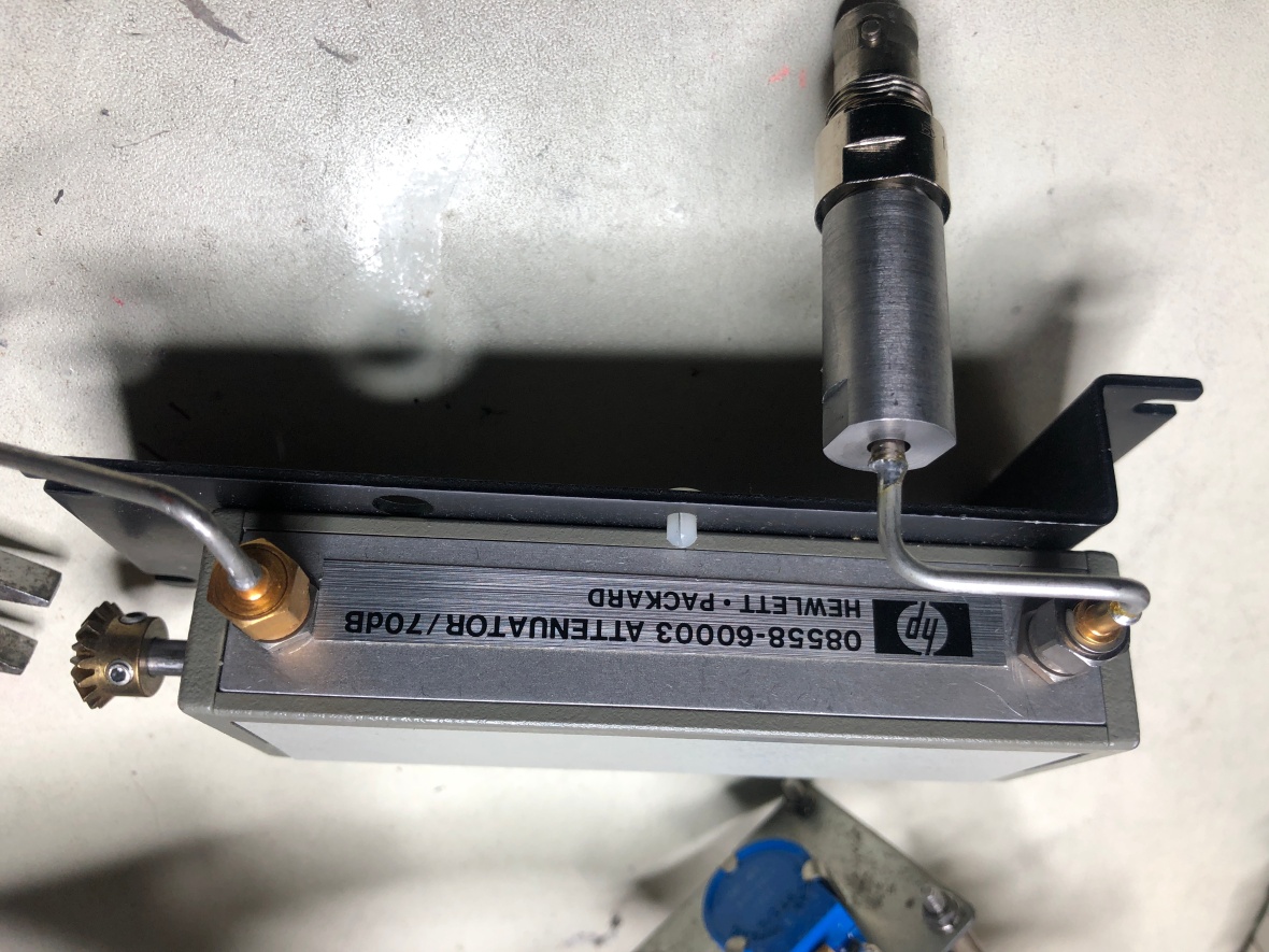
Since I used to work a lot on cars, it was a lot helpful here, as this is mechanical engineering, not really electronics at this point of the restore/repair.
First switch to fix – Trigger source. Had one contact wiper missing.
Here it is, with one tooth.
and after the implant. I revised my design for the contact wiper, to save time and effort as I wanted volume production. Sorry had to adjust the design. 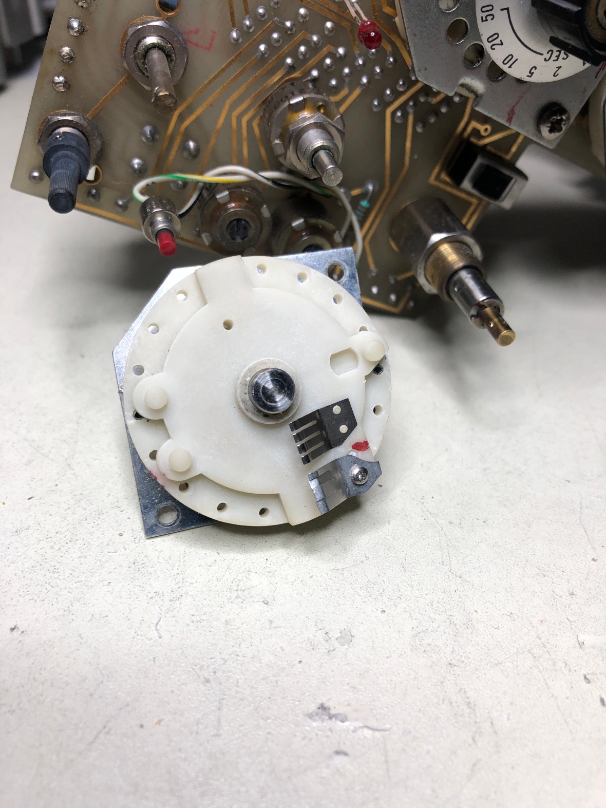
Now is the most painful part. Removing the main combination switch which controls horizontal bandwidth/Div and resolution bandwidth AND constructed on both sides of the PCB, as they can be locked together for optimum setting all around the horizontal ranges.
First fixed the resolution bandwidth switch by removing it from back.
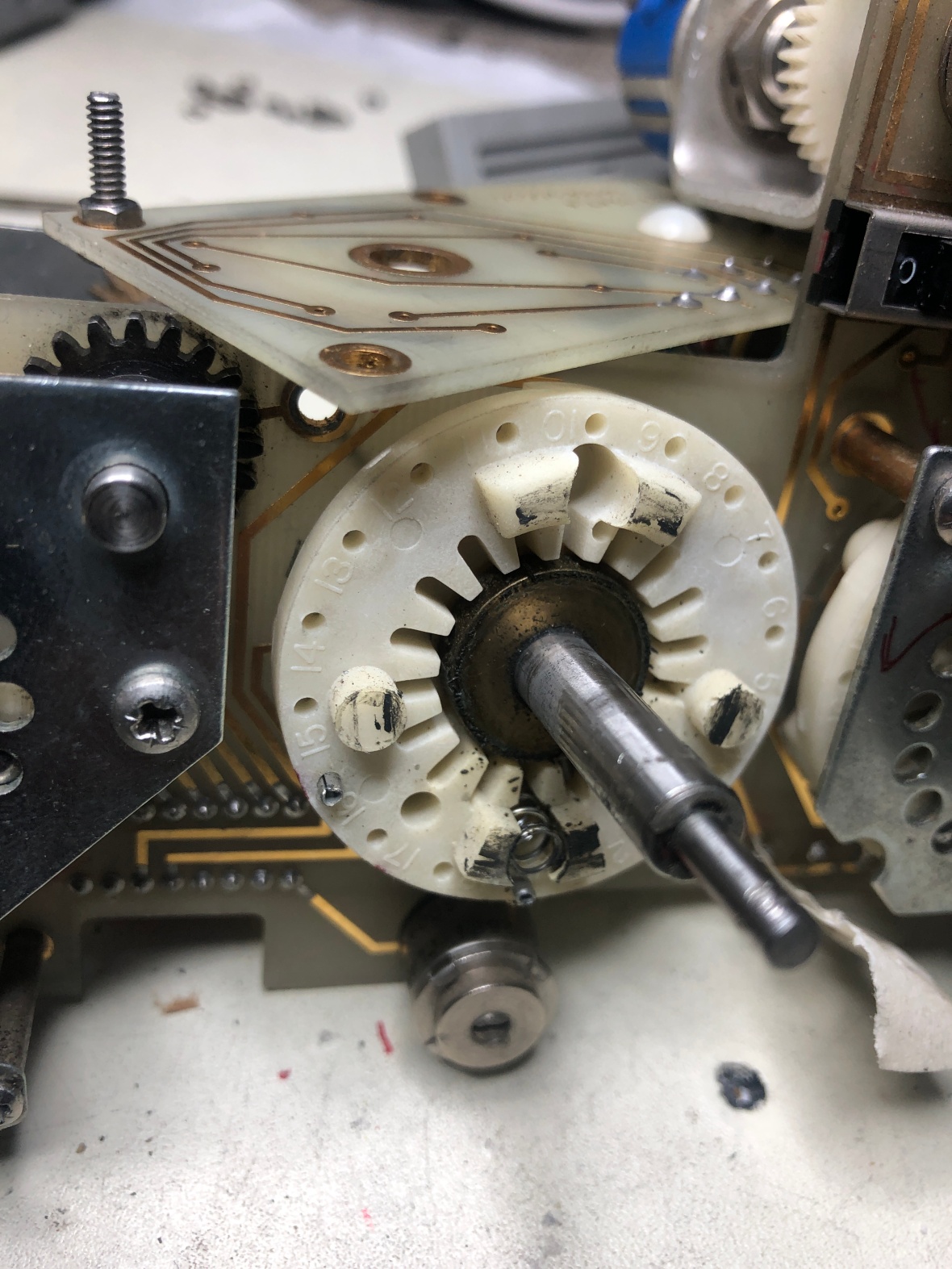
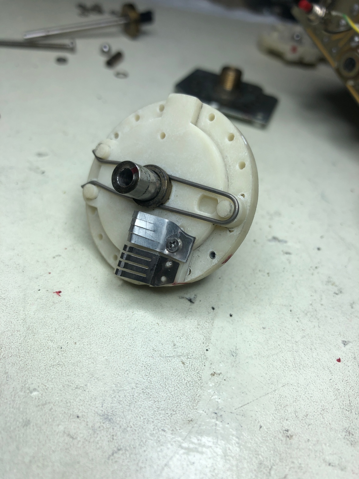
Here is the switch contacts. Its a 4 pole wiper and of course was missing. 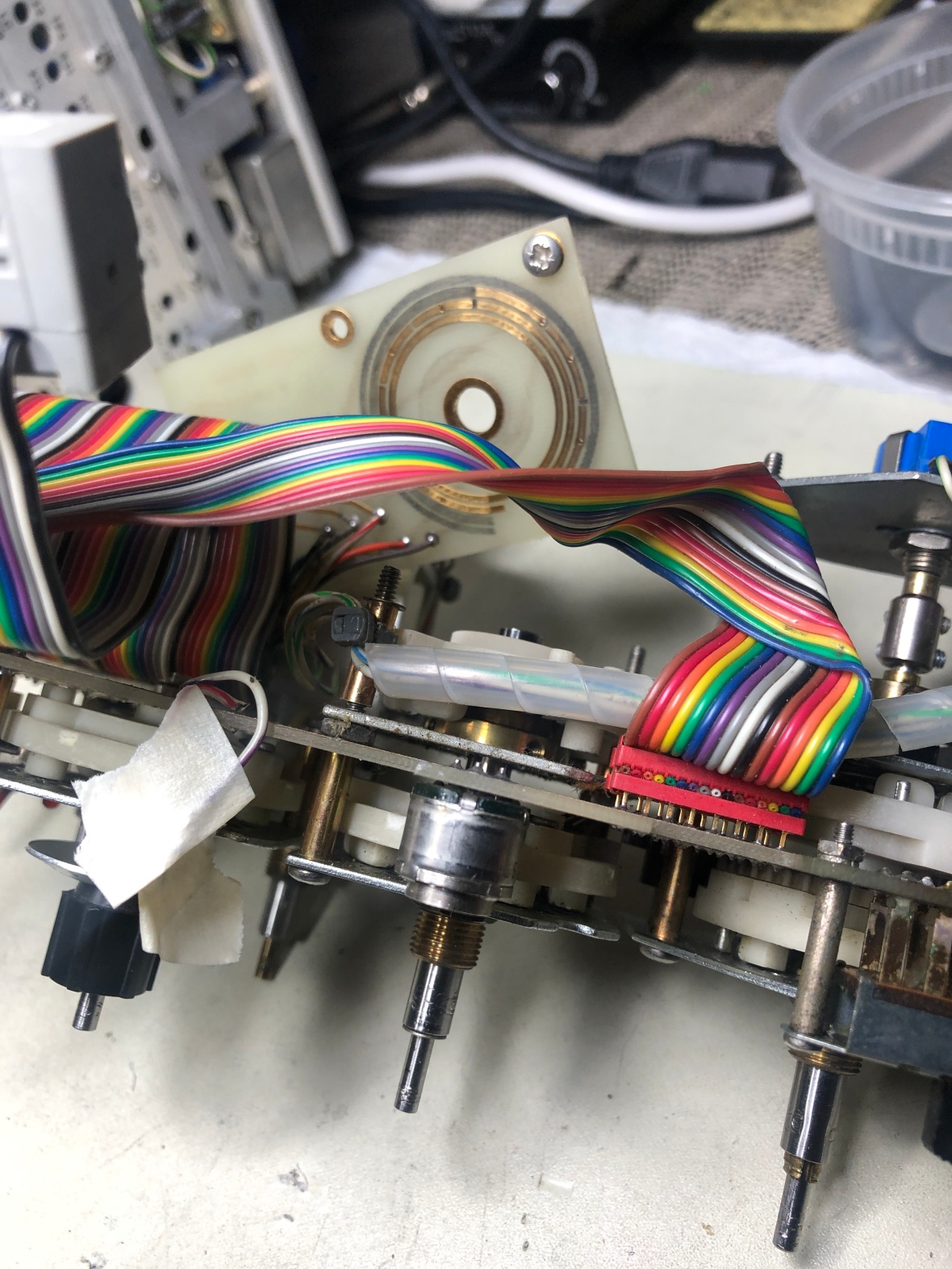
The repaired resolution bandwidth switch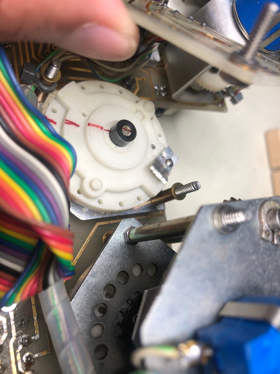
And assembled it back, thinking I can be lucky and remove the front side of the combination switch the same way..but I was not lucky. The entire switch has to be disassembled completely to access the front side for accessing horizontal bandwidth/Div control side of it.
So disassembled it again.
Here is the horizontal bandwidth/Div switch and how it is interlocked to the back with the central shaft.
{{ this reminds me of tata SUVs, to replace a 1$ bushing in suspension, you will have to remove entire suspension assembly, and if you don’t replace the bush it will fail the entire suspension. So most repairs are 10% part and 90% labor, and that is the reason most of the time I used to fix it myself.}}
So here is the final picture of the main complicated convoluted combination switch.
The brass disc you see may not come off easily from the rear of the switch. Blast it away with sledge hammer or rocket. 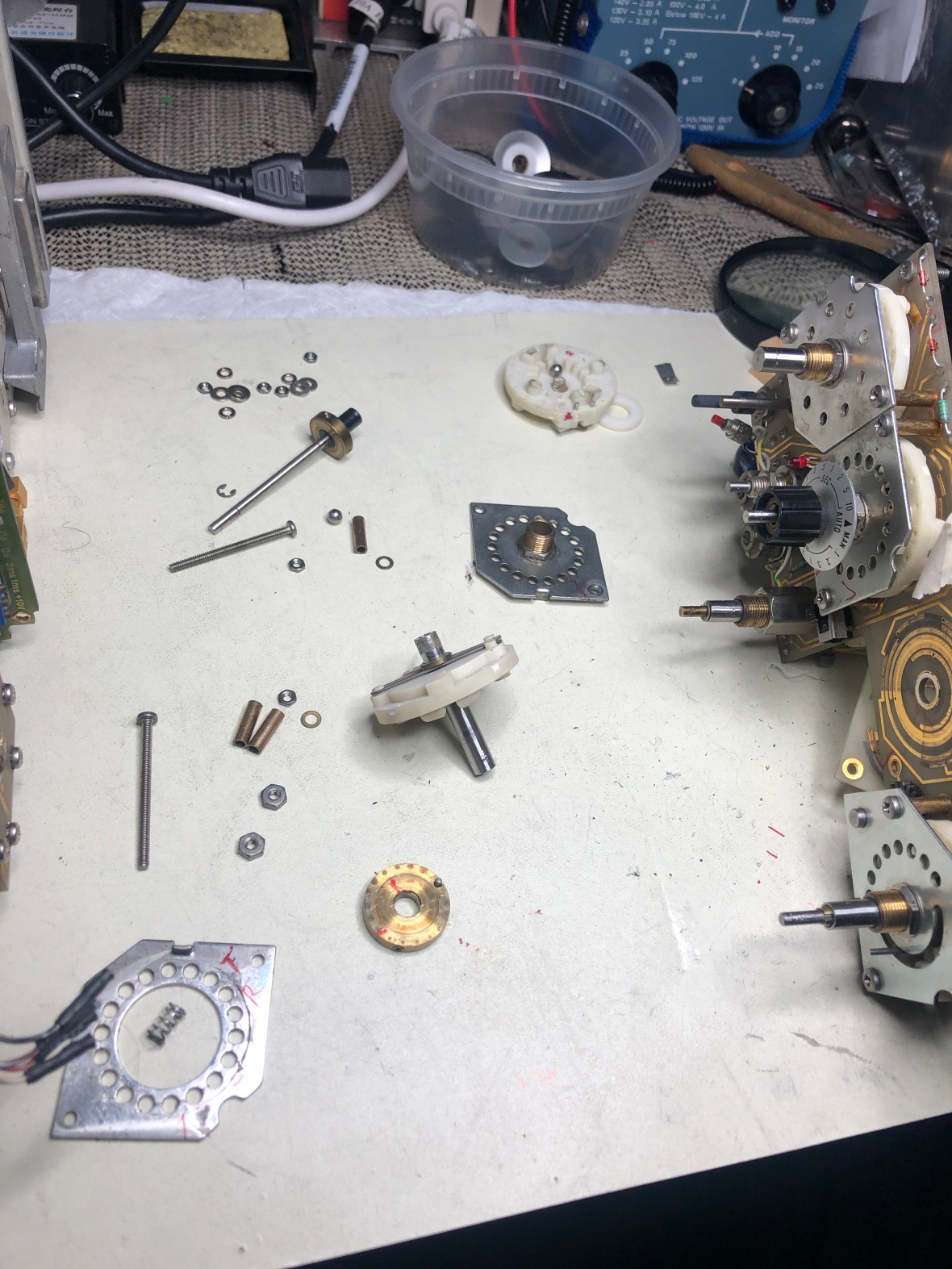
And this is the beauty I was hunting down, as expected she was half empty and half full, but I fixed her
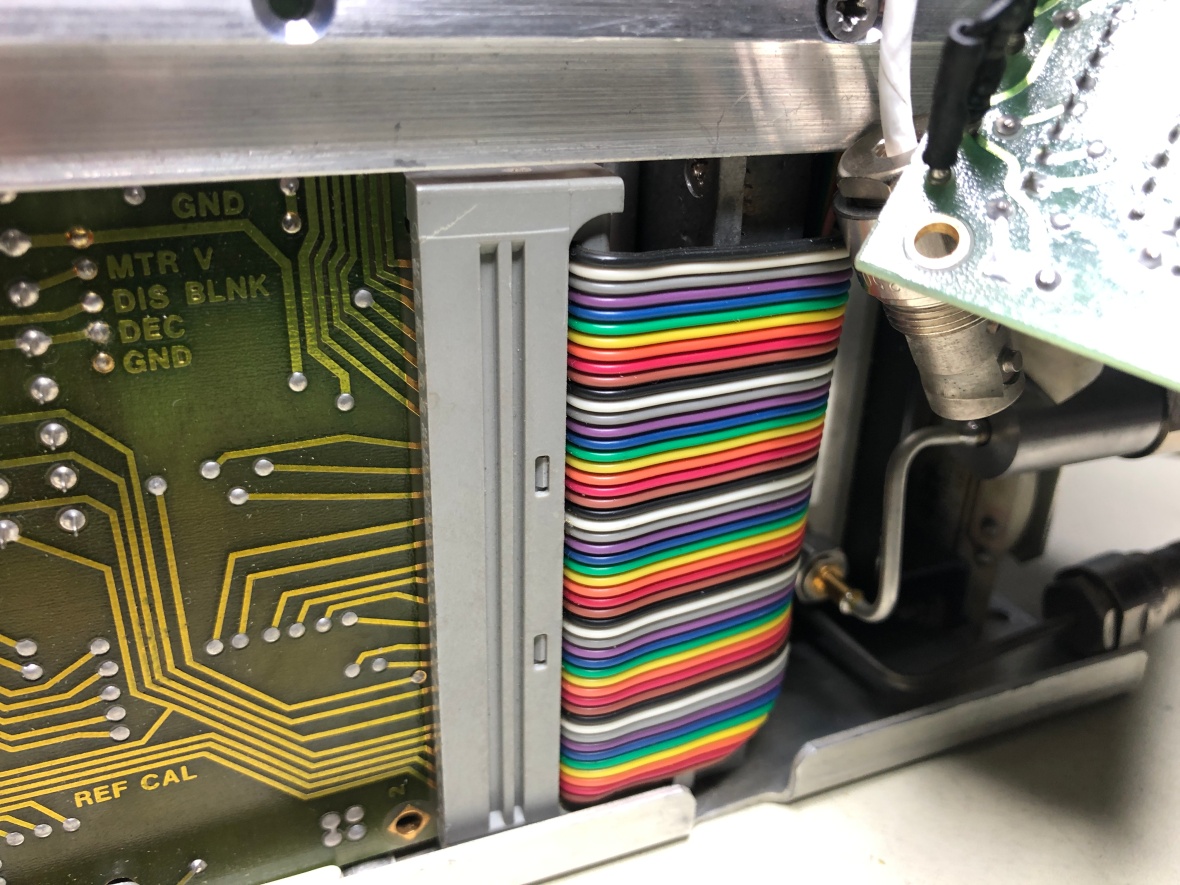
Now putting it all back together. Remember to connect main ribbon cable to PCB at the bottom.
And here it is..and..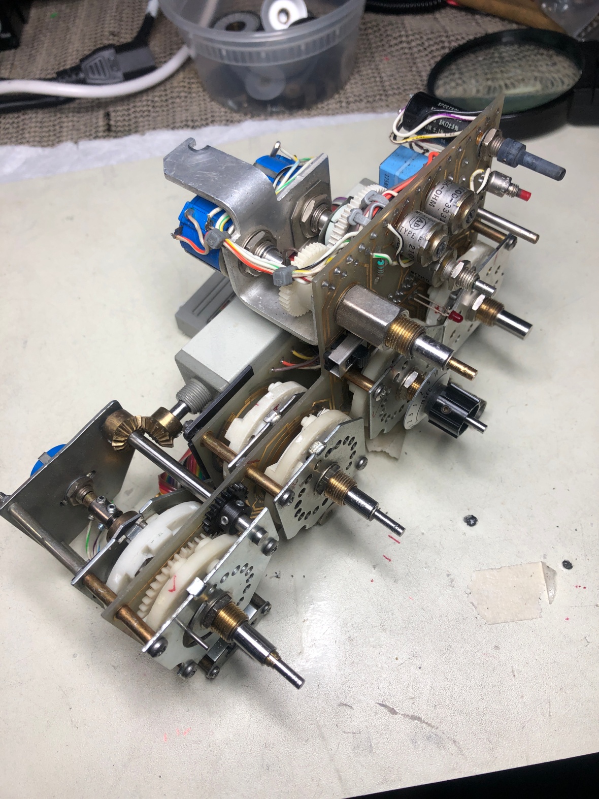
When I tested, the attenuator is not happy. He is too stiff and rigid. had to remove the whole unit again, and lubricate the attenuator shaft and gear assembly and put it back.
 2nd time, front panel is out.
Its 4.00 AM, Time to sleep.
I have glued all the contacts to the nylon base, both the ones I have installed as well as the existing ones to provide some support to ensure they don’t move or fall off.
1/26/19–
Woke up early morning at 11.00AM and straight in to the spectrum analyzer. Aligned, lubricated and fixed the front panel attenuator assembly. Put everything together, did detailed visual inspection. Only 50% of the screws are installed as I am sure there will be more problems. Had to do a bit more
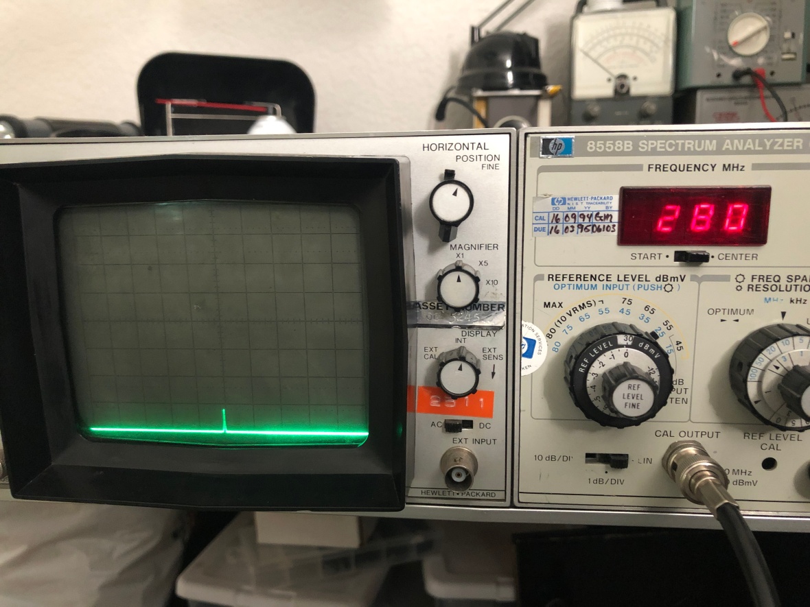
Plugged in to the main frame, CAL out in to Signal input of the spectrum analyzer..and
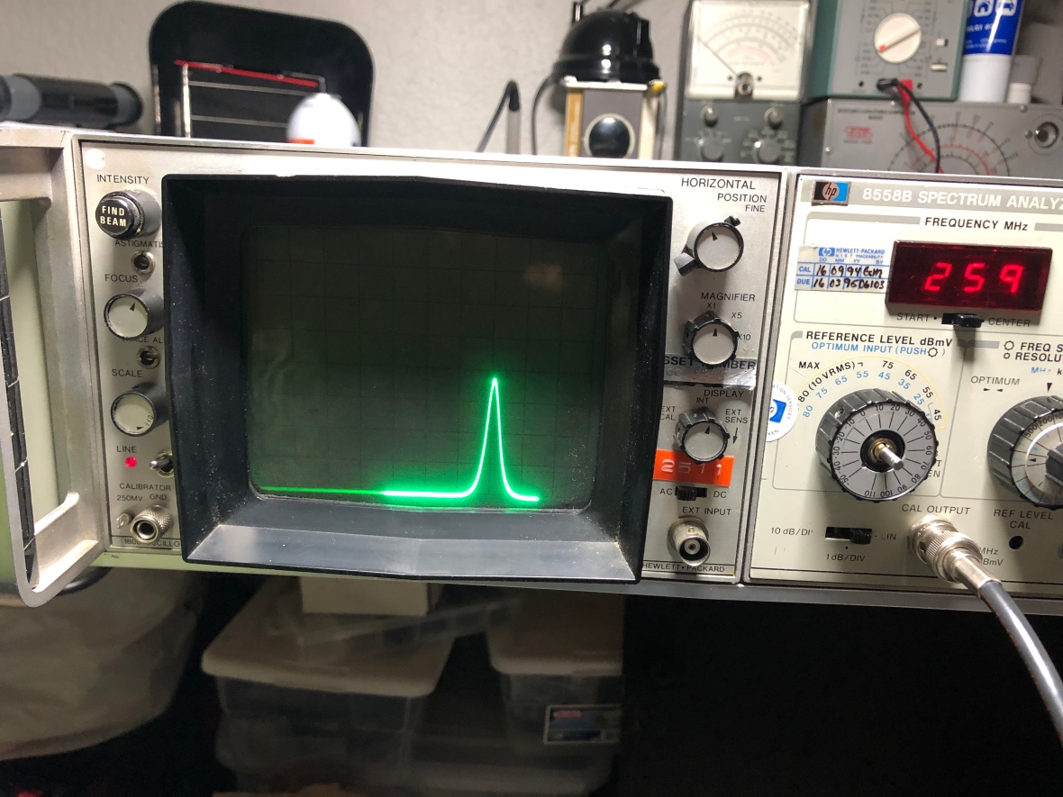
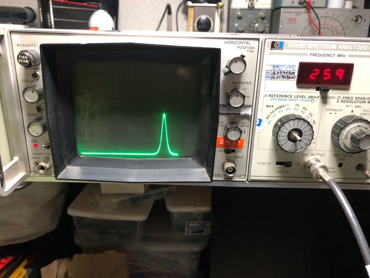
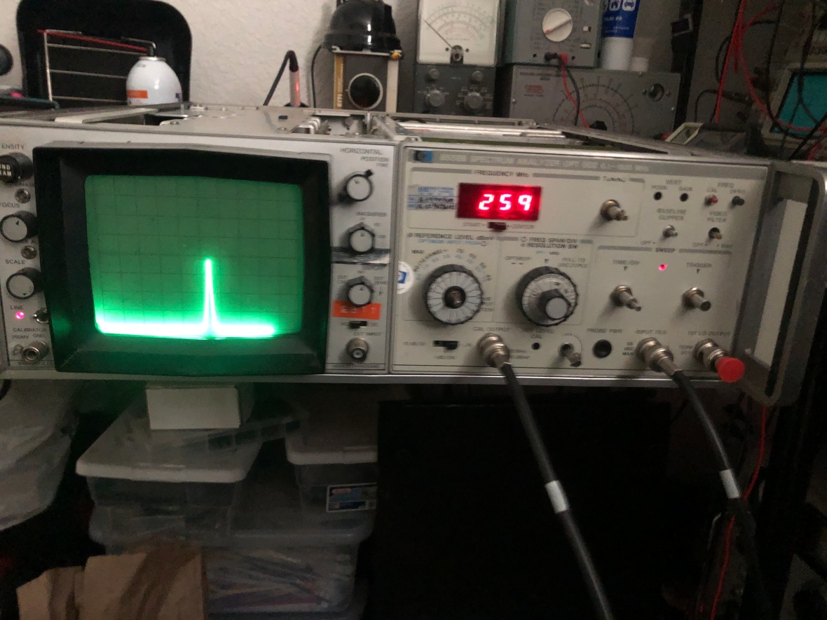
It is BACK TO LIFE..!!!!!!
Well, not yet time for celebration. 280MHz input is recorded as 259, display is not center, and all sort of calibration or alignment errors are there. But its working..
To be continued….if time and patience permits..
27/1/19-
Found few more minor issues like frequency/Div switch and resolution bandwidth was not locking. It was a simple knob alignment issues. Reassembled everything back, not even a single screw outstanding at the end of it 😉
Now, its time to align/calibrate. Since I didn’t poke around with the plug-in RF section or tampered with any settings on the main frame, I was not planning to do a complete calibration. I don’t have all the proper gear to do it.
So all I had to do was a basic adjustment of vertical and horizontal (amplitude and frequency) on the entire unit, as its done generally when you insert a plug-in in to a new chassis. That was all it took to bring the display back in order.
Here are some pictures from the finished restoration.
Remember, this is option 002, 75Ω input version. Do remember all dBmV calculations are for 75Ω
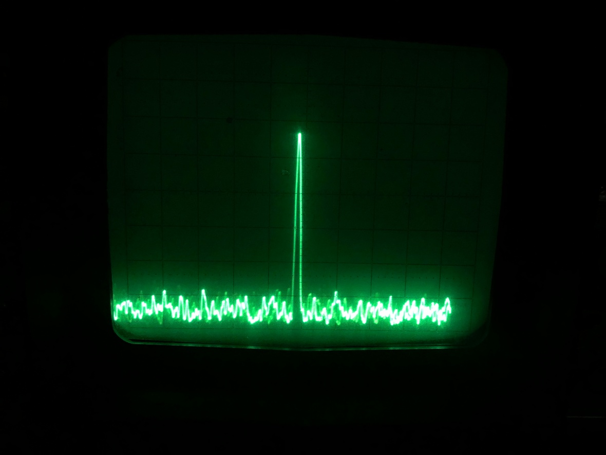
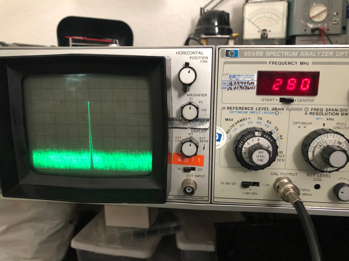
280MHz, calibration signal with same being center frequency.
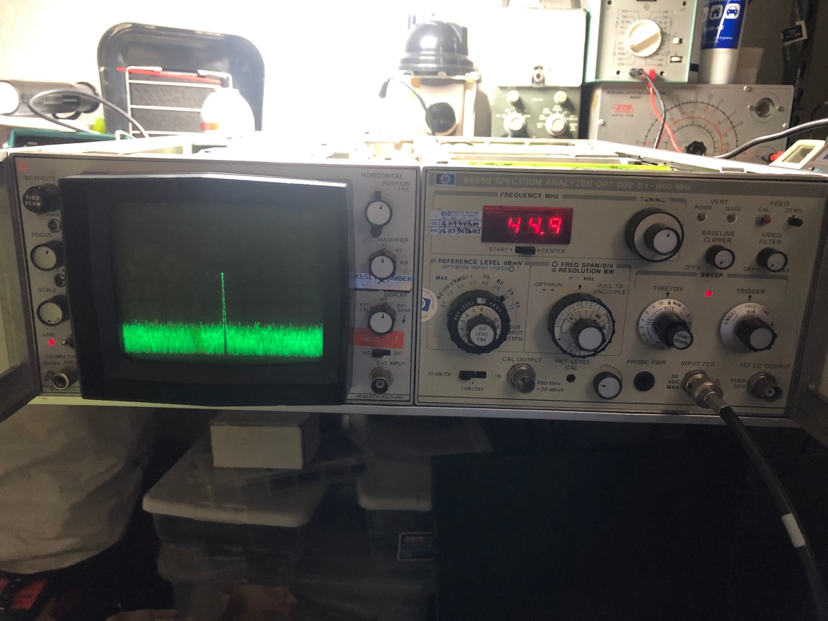
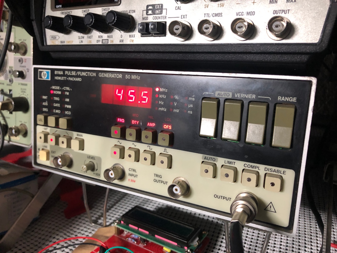
Now a 45Mhz input from my HP 8116A (50Ω output, so keep amplitude minimal to avoid serious SWR, my 75Ω co-ax cable was long)
This is the same one I restored last year, Blog here
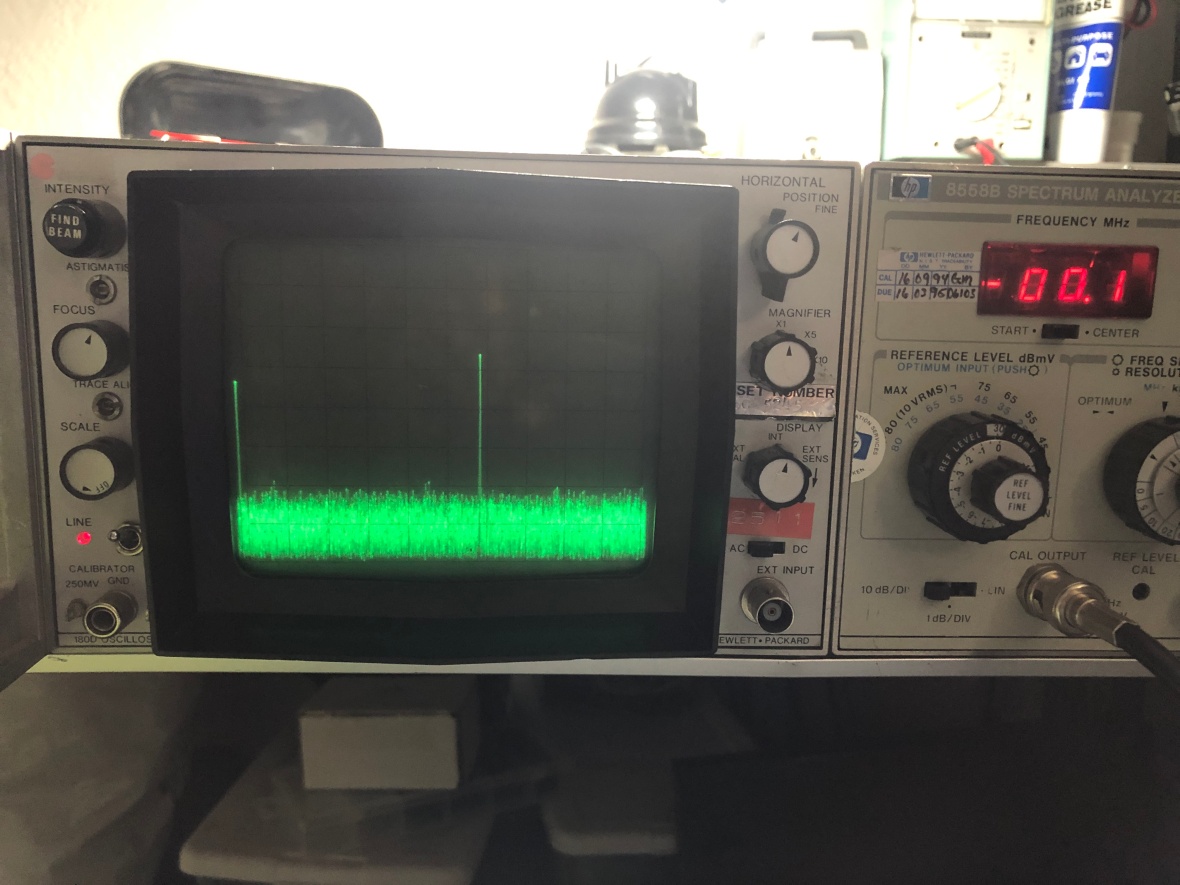
Now with 0MHz being start frequency and 50Mhz/Div Horizontal. Connected CAL out to input, I see the 280Mhz CAL signal very close to 6th vertical line, lower MHz/Div is showing me more accurate value.
Input attenuator settings are slightly confusing with “Optimum Input” and “Maximum input” labels on the knob. The manual changes section in the service manual gives the mapping. Basically full clockwise of the knob is 0dB attenuation and then 10dB attenuation per step counter clockwise. (option 002)
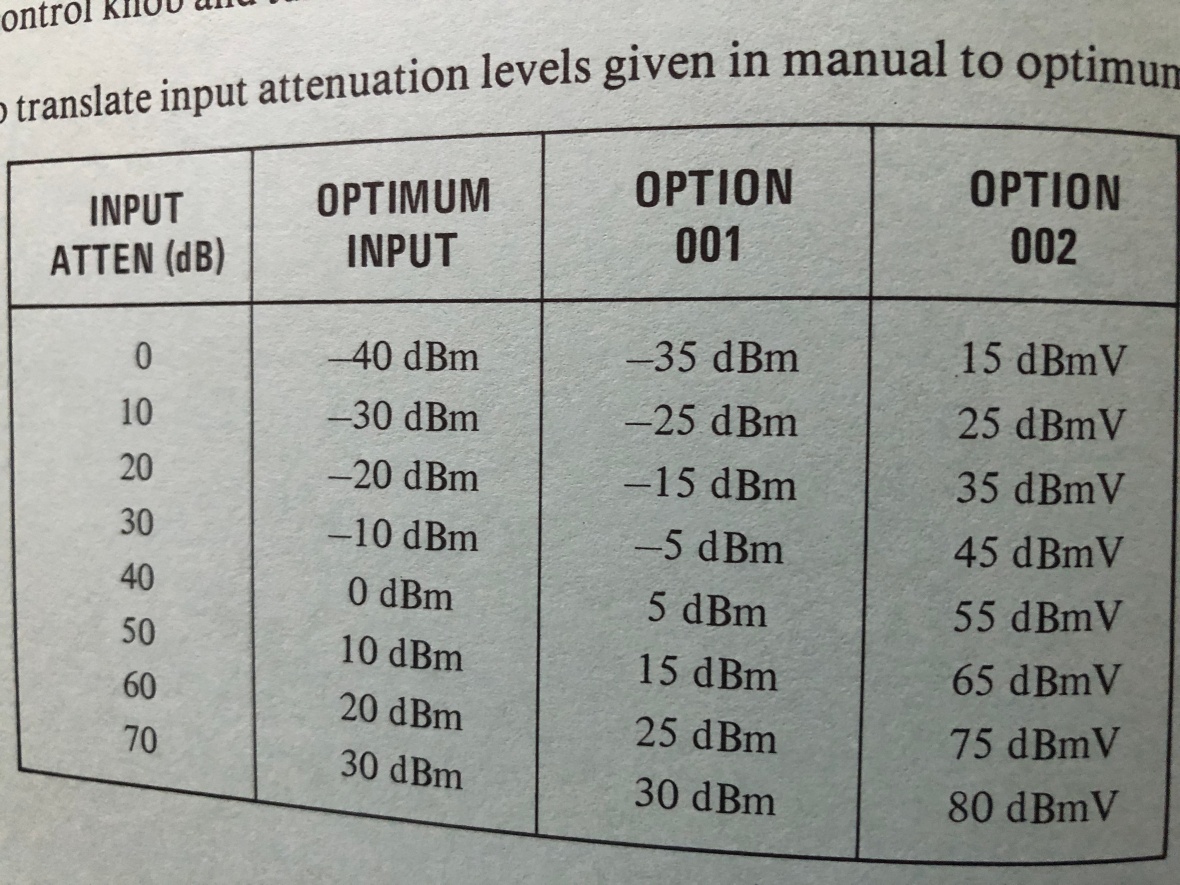
So on the 280MHz/+20dBmV input with 10dB attenuation (aka switch at “optimum input” of 25dBmV) and reference level of 30dBmV, here is the signal. 3 divisions down below top line, as the after -10dB attenuation, its only 10dBmV net reaching the input. Log level of amplitude looks good. That is the switch near the CAL out in the picture, in 10dB/Div.
Lets try Linear mode. Note the switch near CAL out is in LIN position. 10dBmV (20dBmV input – 10dB attenuation) @ 75Ω is ~ 3.1mV rms, reference level is – 30dBmV – is the top most line. So yes, I vertical division is ~ 3mV. { Manual is confusing or wrong in this section of the adjustments?}
All looks good and time to pack this up 🙂
NOTE: The 1st LO (YIG) is free running, so do expect drift during warmup,
In the beginning, I was very optimistic about bringing it back to life, until I saw the condition of the switches. Then I went all the way to being very skeptical as HP instruments have failed me mechanically, like a 2-18GHz sweep I have oscillator, which needs belts, which is impossible to find.
This one somehow I was lucky and in the end and all turned out working, another happy ending.
=== THE END ===

Thank you for your very detailed account to trouble shooting this bit of equipment. I had a friend(?) give me one of these and it has what I am now assuming to be the same failure mode with the rotary switches. It worked for a little while and during the course of me changing settings, it now has lost its horizontal sweep. I’ll pull it apart to look, but if it is the same failure mode, I don’t think I’ve got the ALL THE PATIENCE IN THE WORLD you describe above! Let me know if you’re interested in the analyzer – if it is those switches, you’re welcome to it for spare parts. There are a LOT of unique bits in there that would be VERY hard to come by I would think.
LikeLike
All the best 🙂 I have 3 SAs already so dont need one more ..Thanks Eng.
LikeLike
Hello . Thank you for the info (respect)
I wass wondering what the h signal is? Or how i can generate it just sweep gen?
Hope you can help me
Thanks again
Raymond
LikeLike
Raymod, just use any function generator and select sawtooth wave, or select triangle wave and adjust duty cycle. All you need a wave which has got a positive ramp. H Sweep is basically a sawtooth ramp. HTH
LikeLike
Just find out to put a sinus signal to ext input that gave the trace on the screen..
Only one problem left with the intensity . Its not possible to change it stuck on 100% intensity .
LikeLike
Check CRT biasing ckt for first Grid, you may have open resistors or caps or even diode.
LikeLike
Thanks for the detailed write-up. I grabbed one of these fairly cheap and went through and re-attached all the wipers. One thing I did find that was an issue for me, are the single-wire barrel connectors on the frequency display and the 4 on the front-end near the video filter. Mine were corroded and causing some intermittent issues, I ended up taking a 1mm drill bit and running it through them 3-4 times to clear the black corrosion. Put in some dielectric grease to hopefully slow the onset again and now all is well!
Best
LikeLike
What a massive effort to fix the analyser! I can imagine the feeling of victory in the end.
Those fingers seems to have caused a lot of trouble in HP instruments. For example the
8640B signal generator, along with lots of other front panel problems. Very nice signal generator
but the front panel quality feels more like a cheap clock radio rather than a fine instrument.
I have repaired a HP 8555A spectrum analyser. There is a shaft encoder for the frequency range selector.
It has the same finger and PCB solution. In my analyser the fingers were not broken but had fallen off
the plastic carrier and was found loose inside the scale drum. I glued them back and now the analyser know which
frequency range selected.
LikeLike
It was worth the effort as its a 75 Ohm Unit :). The owner wanted it specifically to monitor TV (analog) signals.
LikeLike
Awesome web site and explanations. Lot’s of pictures that are invaluable!!
Thank you,
Bill Smith
LikeLike
Congratulations for blog. Well done troubleshooting. Best regards, Robert YO4HFU.
LikeLiked by 1 person
Hello,
Very nice documentation.
i recovered an HP182T oscilloscope with an HP 8558B drawer.
I fixed the power supply to the oscilloscope, a Zener was to be replaced.
I have two questions:
Without putting the drawer, the beam finder works, the focus too, but the intensity does not seem to vary. (I see the spot).
normal or not?
For the drawer 8558B, there is no horizontal sweep (on the oscillo) and nothing in the displays. the A8 card gives the sweep in test point. But my main problem is the documentation.
The serial number of the analyzer is 1321Axxxx, and I cannot find the documentation on net, only before 1985/86. –>> not the same display!!
the good documentation is:
HP 8558B Operation and Service Manual dated October 1977, HP Part Number 08558-90043
If you have it, you can send it to me
thank you
LikeLike
I’m sorry I don’t have the manual for the old rev. Intensity should vary with adjustment. Check the pot itself and the rest of the bias resistors for the CRT intensity control. Sometimes you can use the existing manual as a reference and the changes will be minor (not always though).
LikeLike
Sorry, rectification, the documentation i found is after 1985/86. It’s before i have to found
LikeLike
You did good! Brilliant. That 8558B job was not for the faint-hearted
LikeLike
Thank you Symon! It was intimidating 🙂
LikeLike
Hello Lazyelectrons
Congratulations for your job
I have Hp 180c and hp 8558b
This spectrum analyser was good until yesterday…!
The first problem was about the low voltage regulator : the current limiter transistor dead short circuit between pins : no 100V
no 15V no -12,6V and no -100V
I change this transistor with an equivalent . I control on the test points All is Ok
On the screen the trace is ok on the bottom
After one hour the trace is now on the middle of the screen ! I try to set by the Vert Pos potentiometer ..no result
Please Can you tell me what do you think about and what I do to solve this problem
Thanks
Regards
LikeLike
Thank you!
I would suggest that you remove the 8558b from the 180C frame. Then confirm all power supply rails are good. Then move the V pos to the midpoint and check the voltage on both the V-Deflection plates of the CRT. Compare it with the schematic and that will point you to the offending side (push/pull) of the v-def amplifier. Once identified, you can isolate the problem within that section by measuring/comparing the voltages at the reference points as specified in the manual. Hope this helps. All the best.
LikeLike
Useful writeup – have just done the same on a 50 ohm 8558B here and also had to cut a new pair of 48dp gears for the main coarse tuning. The service manual instructions on rebuilding the switches are thankfully good (and someone had clearly dismantled mine before and mixed up some parts between ref level and freq span/div switches). For those of us in metric land M1 screws 3mm long work well to secure the fingers. Attenuator remains rather stiff.
LikeLiked by 1 person