This spectrum analyzer was part of the whole rack of spectrum analyzers I purchased on a day where I was not very normal.
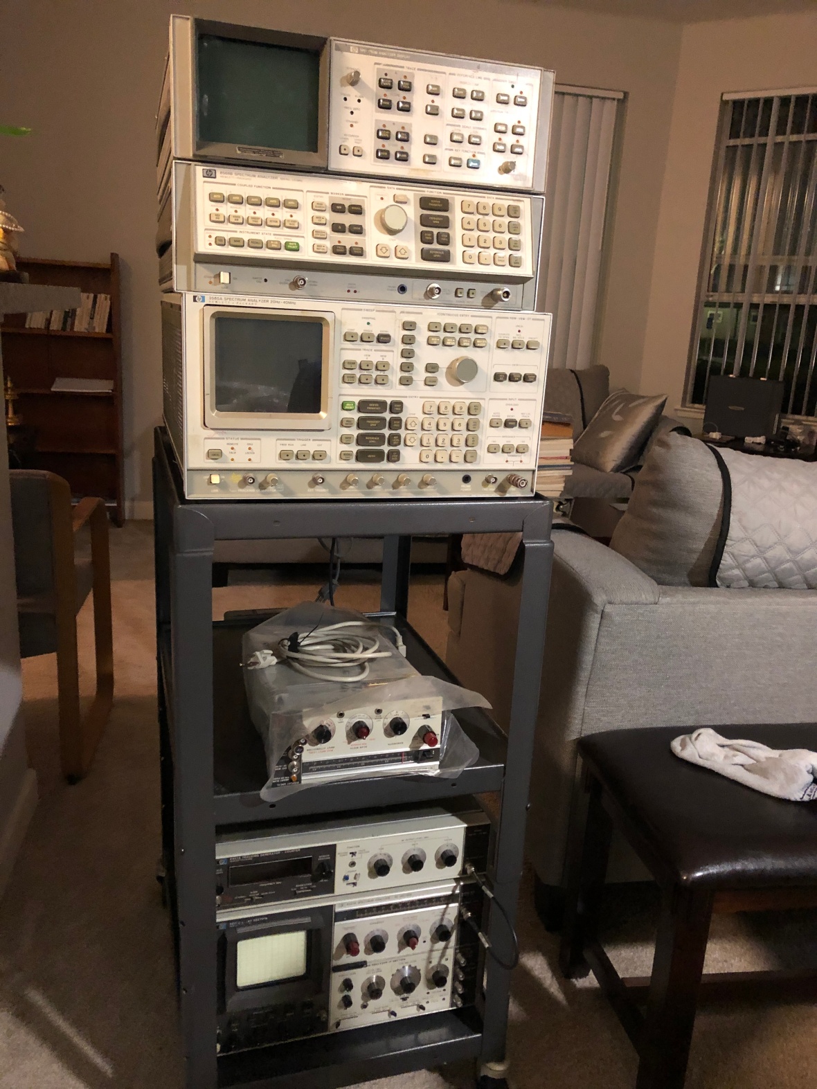
All three were faulty and I fixed all three of them over the past few months. Documenting was pending for long. I was lucky that none of them had serious troubles such as YIGs or other unobtainums.
I was not lucky on the tracking Generator – 8443. The ALC board/A8 have a bad RF AMP HP hybrid. To be covered in a separate write up on how to troubleshoot this fella.
Coming back to 141T, since it was not being used for a while, the usual ritual of extensive cleaning, visual inspection and testing basic power supply was performed. All caps except few were reformed successfully. I had to replace few caps as it was showing excessive leak. If you want to know the details on cap reforming, check my HP 608C or Tektronix 575 repair write up.
The power supply main filter caps
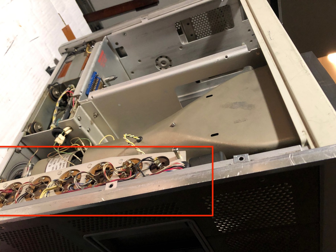
Now further inspection showed more trouble.
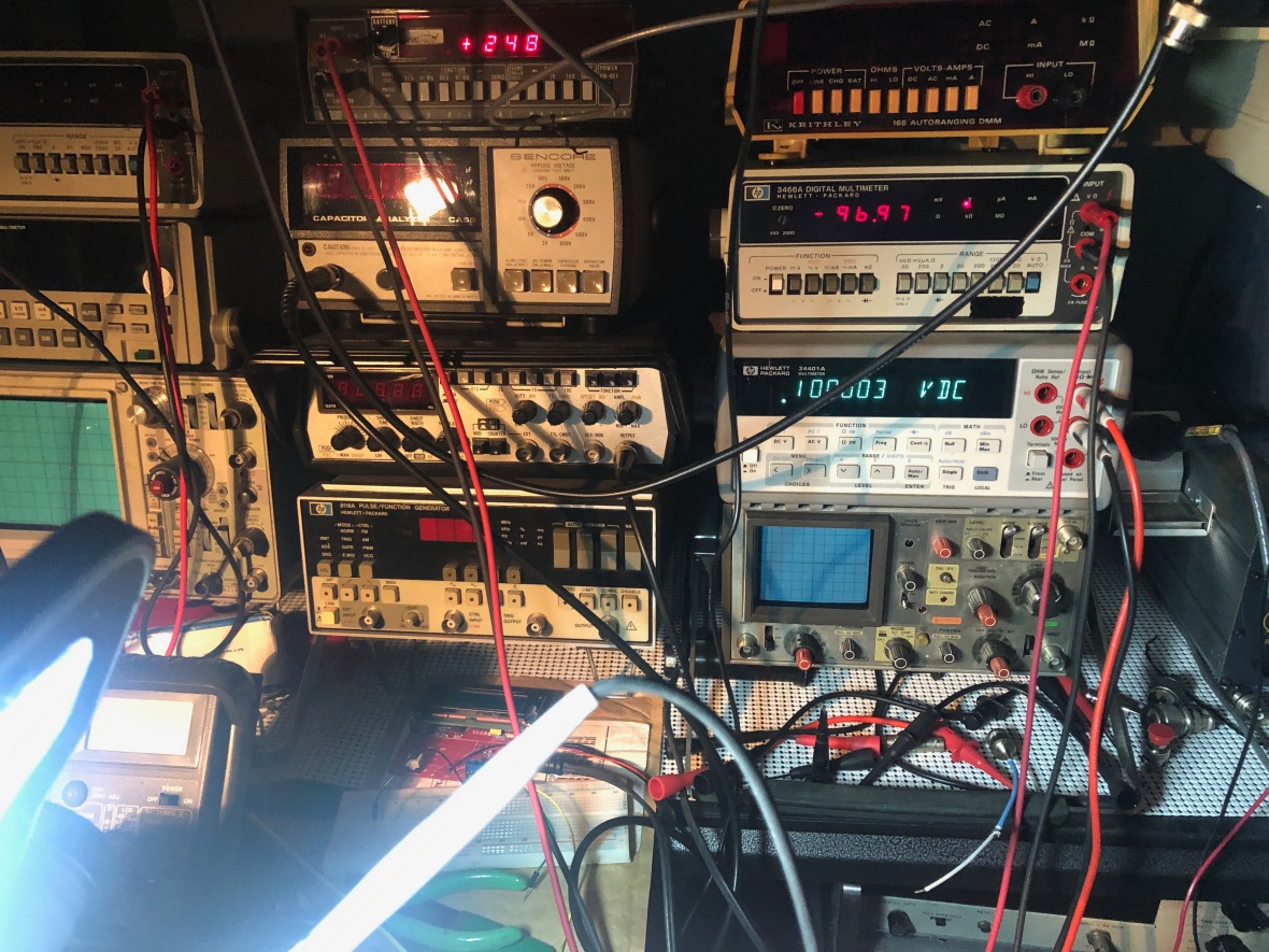
Problem #1 : -100V rail can not be adjusted. Max is -96V
In case you want to see more of the operation table and the patient, here it is.
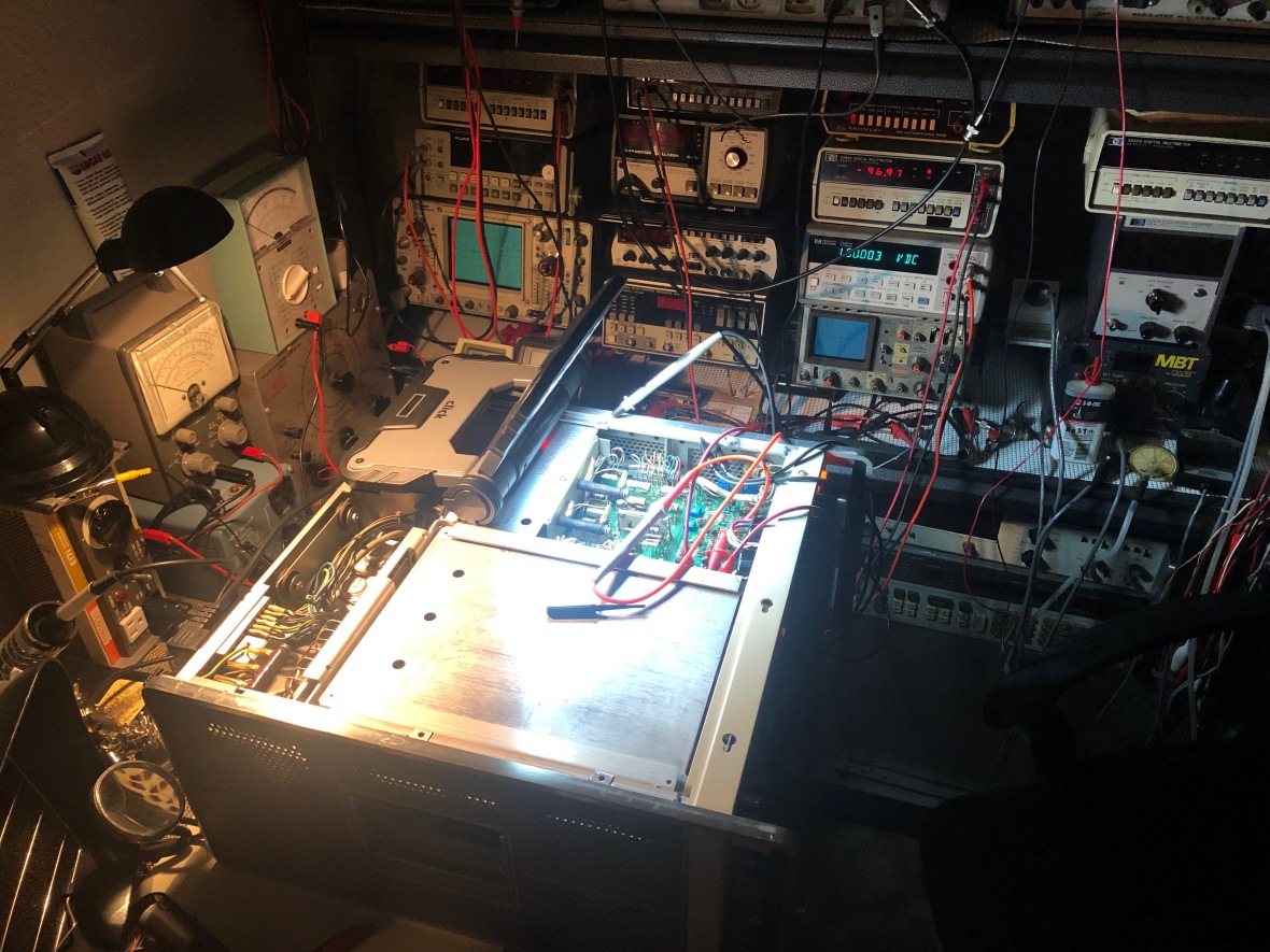
Now to fixing this.
SAFETY FIRST ::
DO NOT ATTEMPT TO REPAIR/OPEN/OPERATE/FOLLOW UNLESS YOU REALLY KNOW WHAT YOU ARE GETTING IN TO. THERE ARE DEADLY VOLTAGES INVOLVED AND IT CAN KILL YOU.
THERE ARE BETTER WAYS TO DIE IF YOU ARE UP TO THAT.
Even if you are familiar with electronics, be very careful when you work on something like this, a maximum potential difference of 400V DC is present in this equipment. -100V,+100V,+248 are the DC power rails inside. DO TAKE CARE. CRT HV from cathode to anode is ~9000V.
The neon voltage regulator tube uses KR-85 stabilizers to help the starting. Even though the half life period of this radioactive substance is 10 years, I want to explicitly state the warning in case you are worried about such stuff.
The power supply have multiple revisions with significant changes in design from VR Tube (Neon) to zener and changes in rail reference. Make sure you are verifying your serial no# and referring the correct schematic. There is a HP141T manual change document available online which explains all the changes.
So my unit had VR tube for reference @ 82V+/-1V, +100 being main regulated rail and then -100V rail regulated from +100. +12.6 and +248 is referenced to -100.
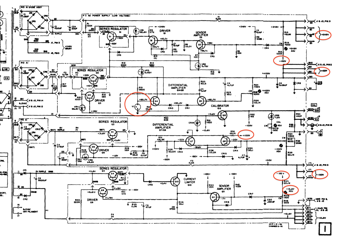
So it is interesting to note that even though -100V rail was 4V below the required at the maxim position of the voltage adjustment pot, the +12.6 and +248 were adjustable and was able to calibrate them to required spec.
This is very similar to the Tektronix 500 series design for power supplies. Bit more complex here as its a recursive reference, ie +100 to -100 which then provides reference +12.6 and +248. Tek does -150V common reference for all rails. Check my Tektronix 547 or 549 restoration blog for details.
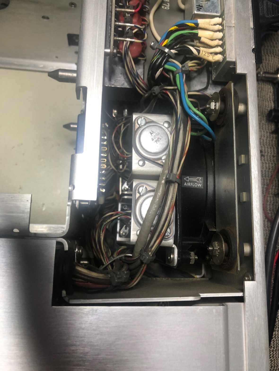
I did the usual check around caps, series pass transistors and driver transistors etc and all were found okay.
In case you suspect the series pass transistor, you can swap it from another rail and verify. They are mounted behind the unit and right next to fan. Beautiful design and well documented in service manual.
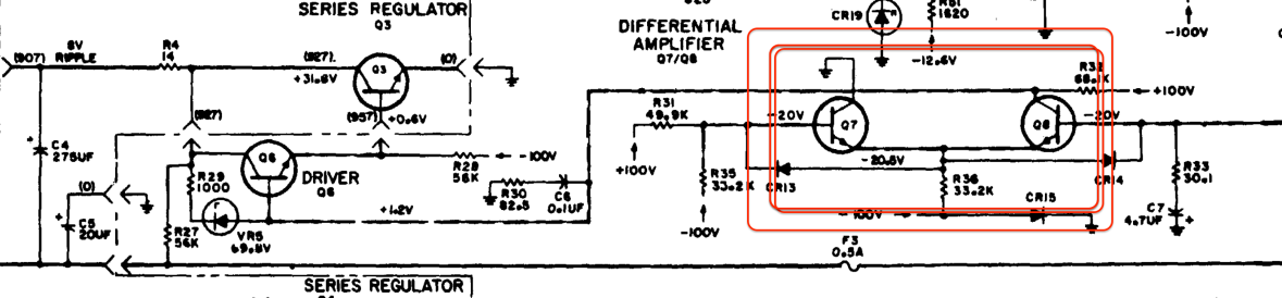
Here is the detailed diagram for -100V, basic regulated design with series pass, driver and comparator.
Every active component tested out working. But output will not go to -100V.
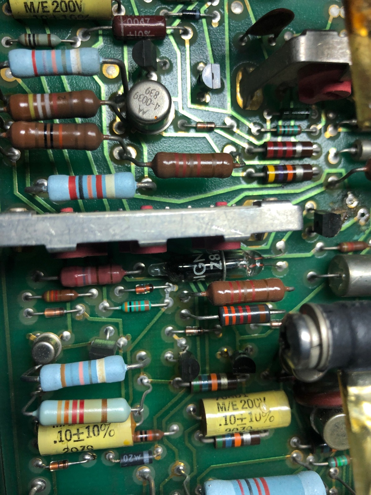
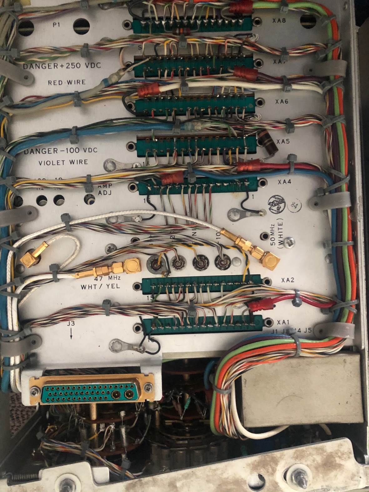
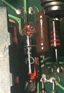
If you carefully check the values of the resistors involves in the design, most of them are @ 1% tolerance. I started measuring them around -100V regulator and most of them were way off,up to 20%.
If you are not careful, you would assume they are in and fine, but they are NOT. I had to replace a whole bunch of resistors from this section as all of them were way beyond 10% drift. They are 1% metal film resistors as per the parts list.
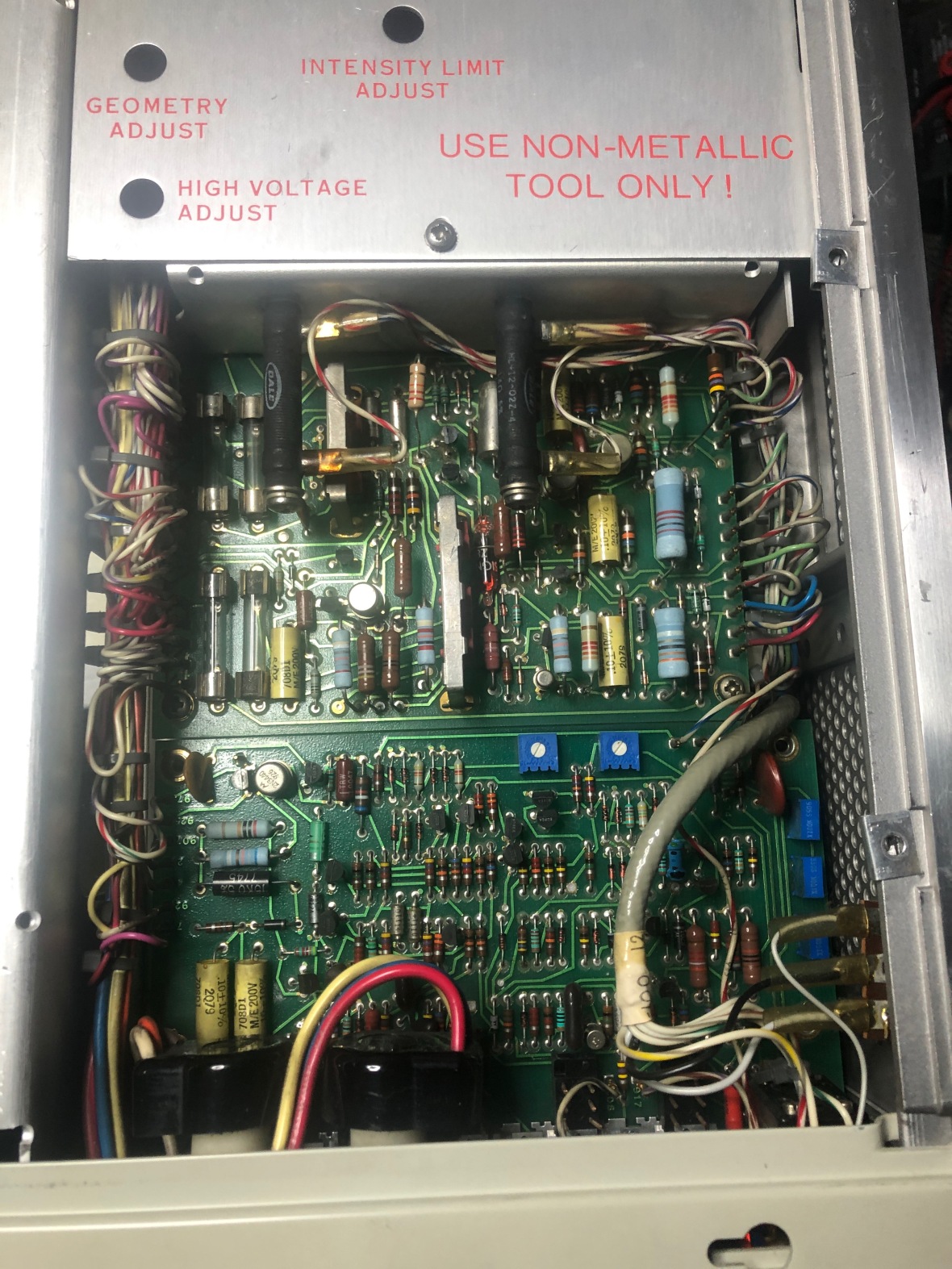
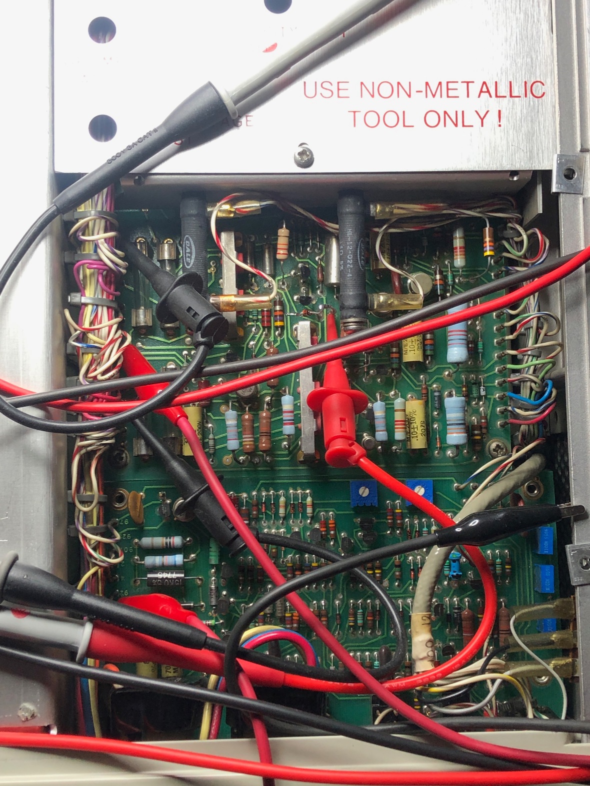
Watch carefully with the schematic, most of the critical resistors are 1% and others are 5 or 10% tolerance. Here is the picture of the board.
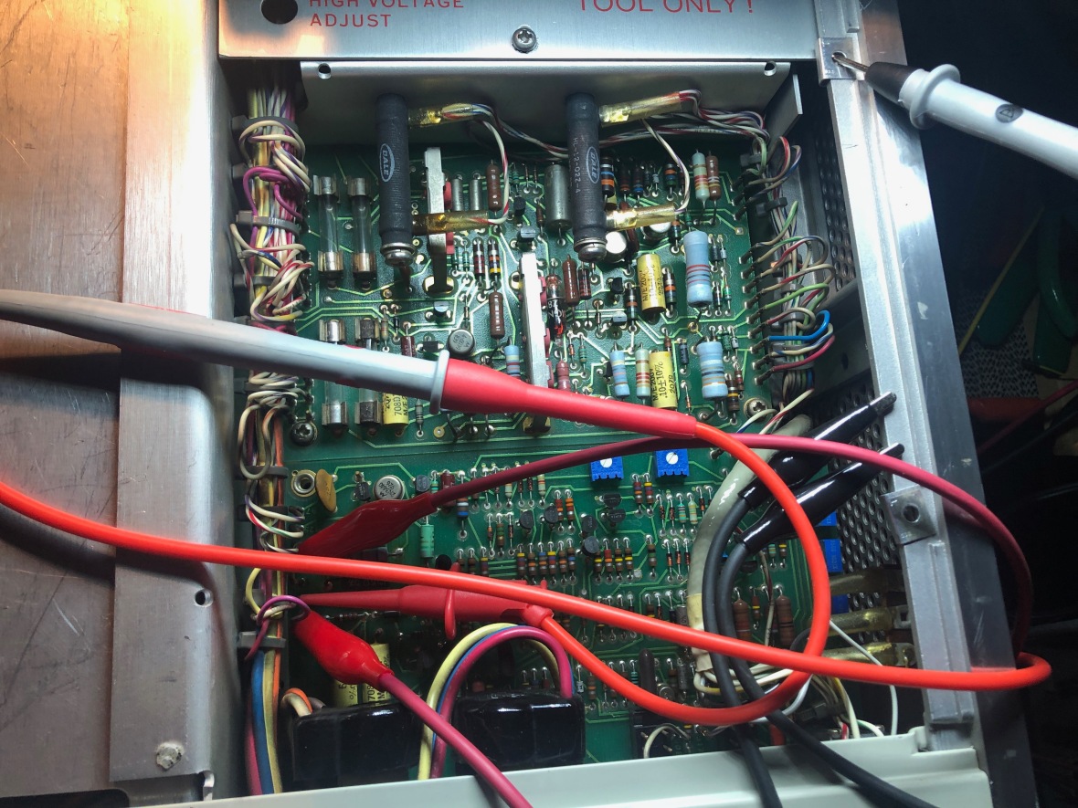
These are the ones to watch out for specially in the differential amplifier/comparator section. But recommend checking all if you are in.
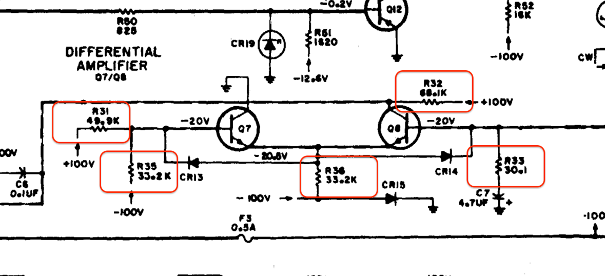
Now they are weird value 1% precision resistors. I had an easy solution. Scroll through the box of carbon composition of closest standard value with my HP 34401 and find the best. eg. 33.2 was found from 33K/5% pile, 30K was found in 27K/10% pile, and 49.9K from a 47K pile.
Here is the board after replacing the resistors. I left all the new resistors up high in the air to help with cooling in case they get hot.
Now, -100V rail is fixed I am able to adjust all the rails to spec. Remember to load the plug-ins and warm up before calibrating the power supply.
Problem #2 : Low Signal Level.
I started testing the SA with my plugins. I got two plug-ins with the kit. 8553B and 8555A. 110Mhz and 18GHz RF plug-ins.


Surprisingly, both the plug-ins were working but showing very low amplitude. ~ 20dB down the expected. The good part is it is not the RF plug-in as both of them were having same issue, but the bad part is if the IF module is bad, I am in trouble.
Started looking around for problems and this was a real easy one.
The RF and IF plug-ins are electrically mated using a D Connector.
Here are the details from the original manual of 8555A
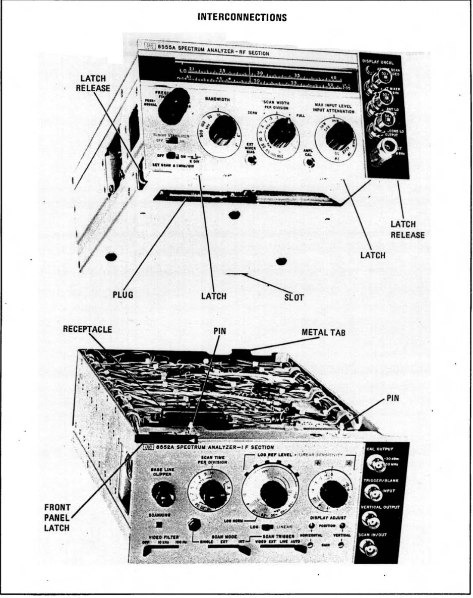
Here is how it is in color.
RF Module
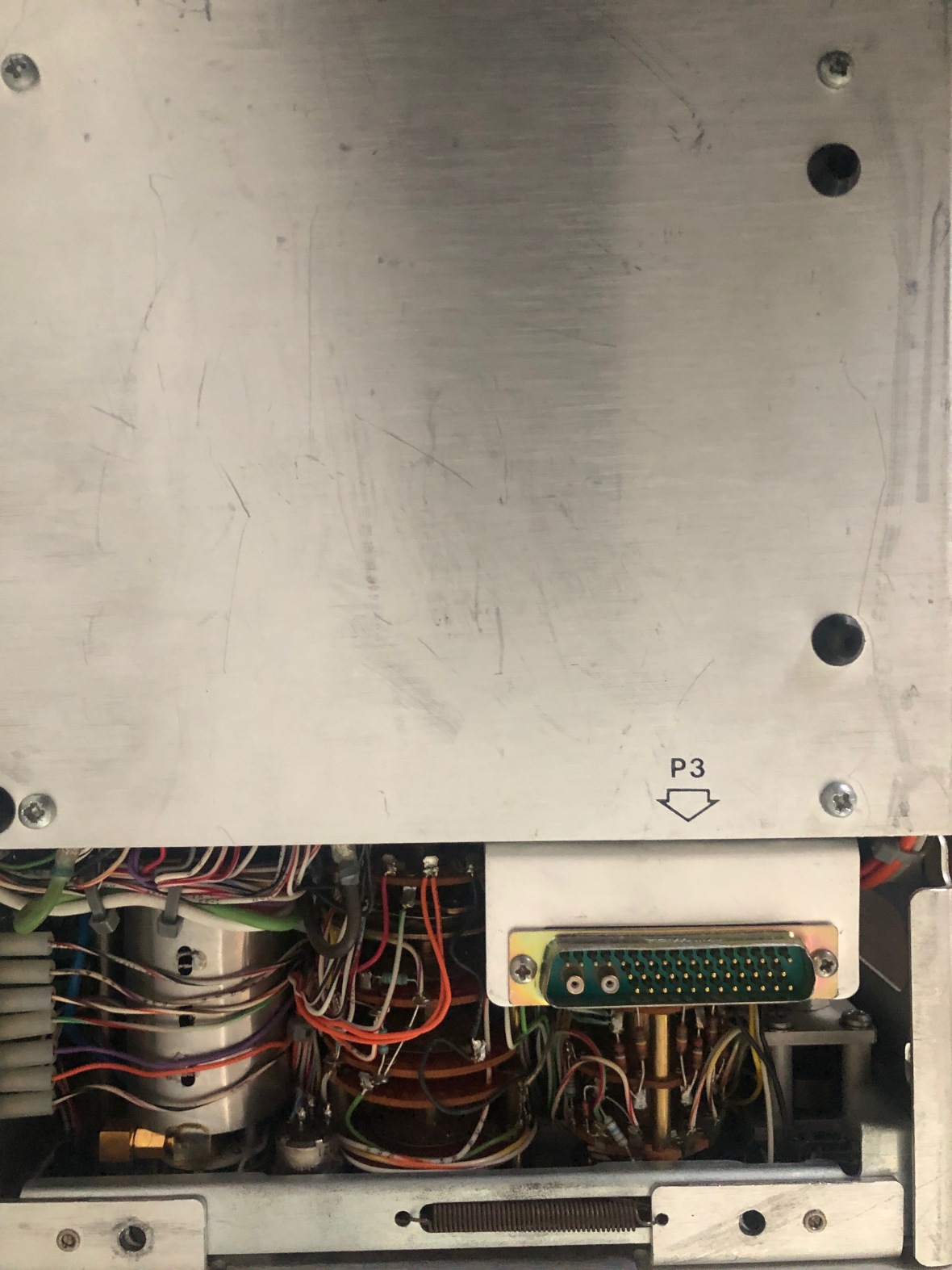
IF Module
And how they mate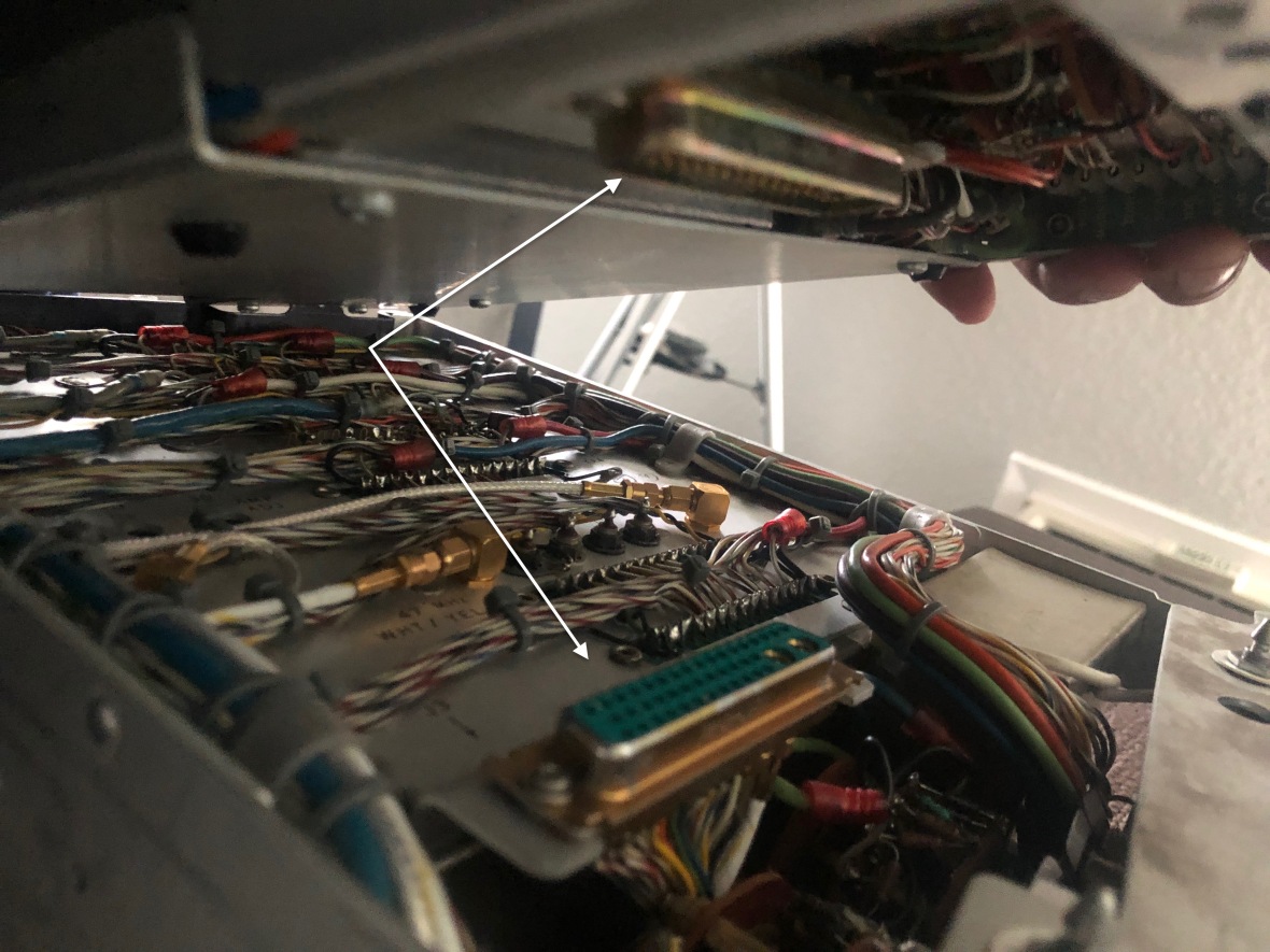
I noticed that there is a gap between the D-connectors and they were not seated properly. Found a slight bend in the IF plug-in connector and readjusted the lips with nose plier and mated the modules again..and here is it..all amplitudes are up to spec.
What you see here is the 8553B with 30Mhz calibration signal @ -30dB
{remember to follow the adjustment procedures in the manual after mating the RF & IF plug-ins}
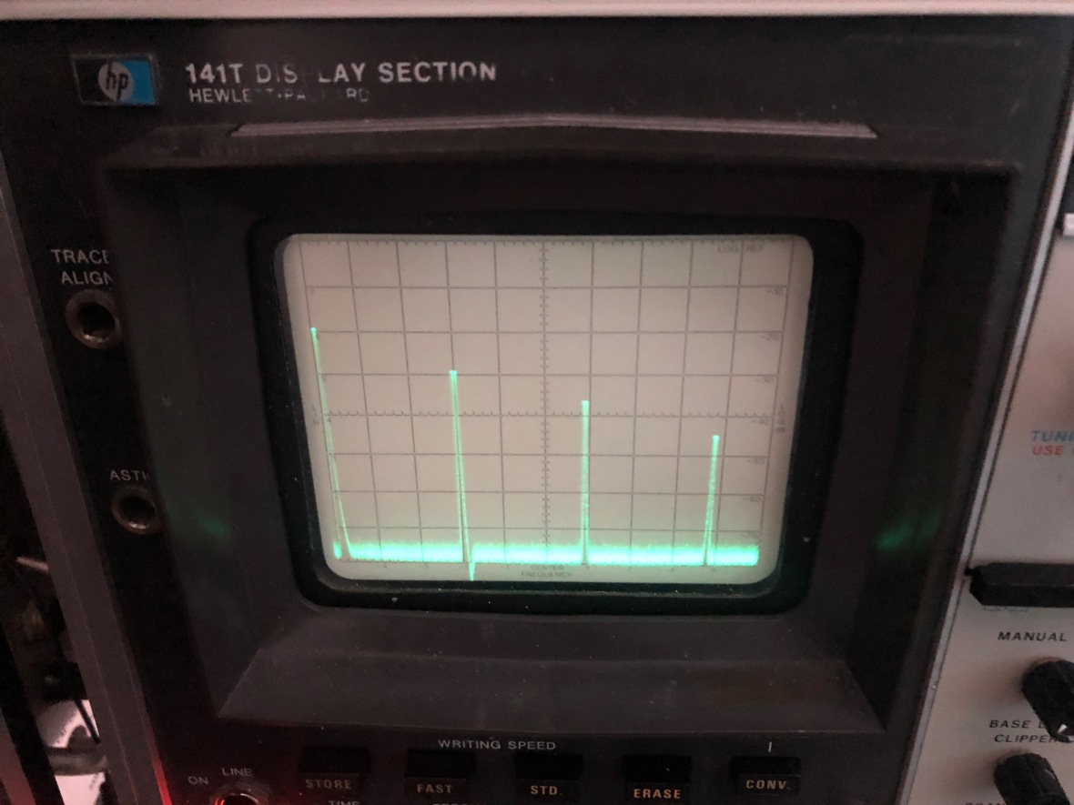
and Reference level at 0dB
Now, lets sniff the air around for waves….here is my favorite 94.5 Bay FM 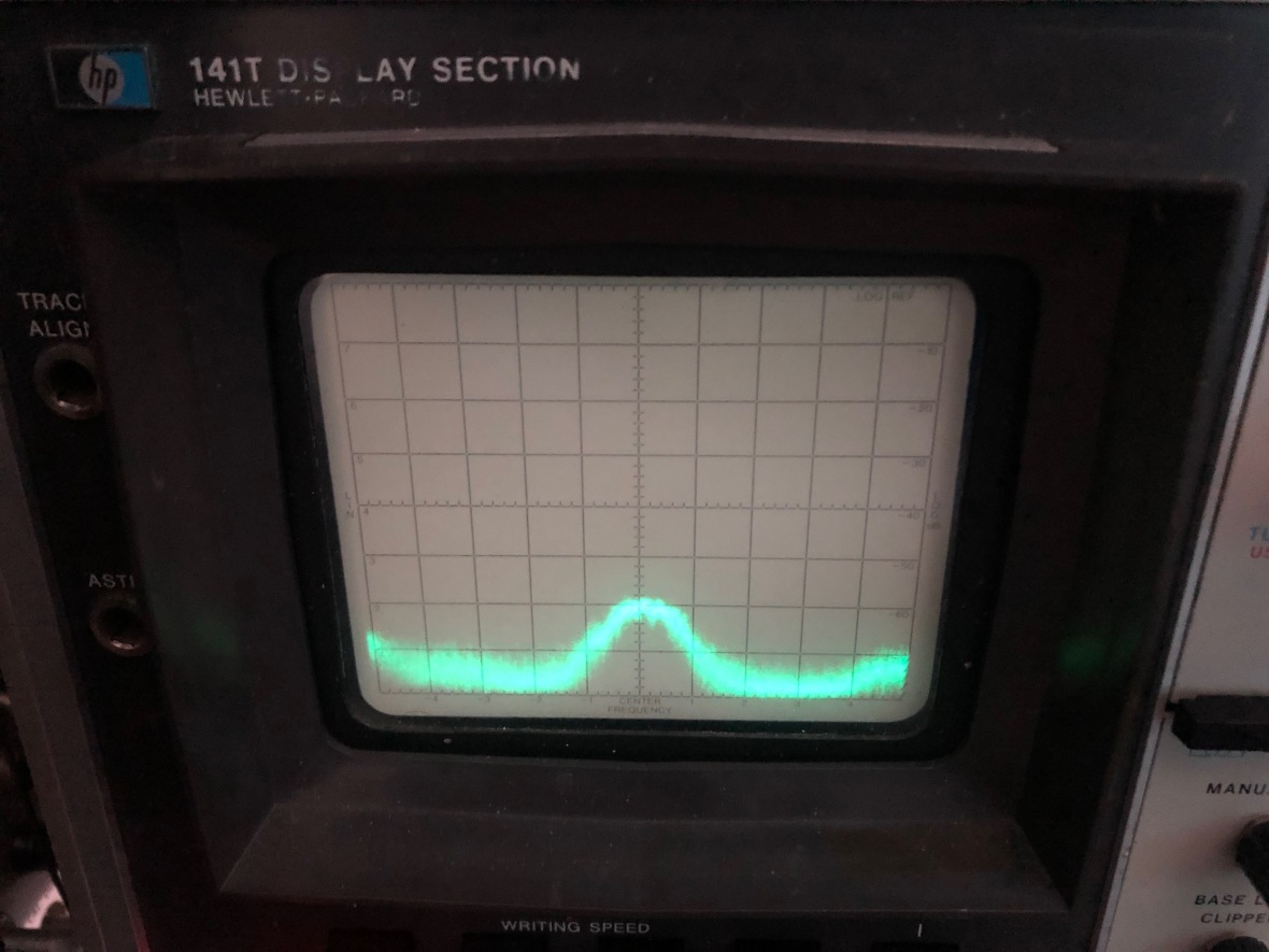
And one of the local AM stations around 1100 KHz. 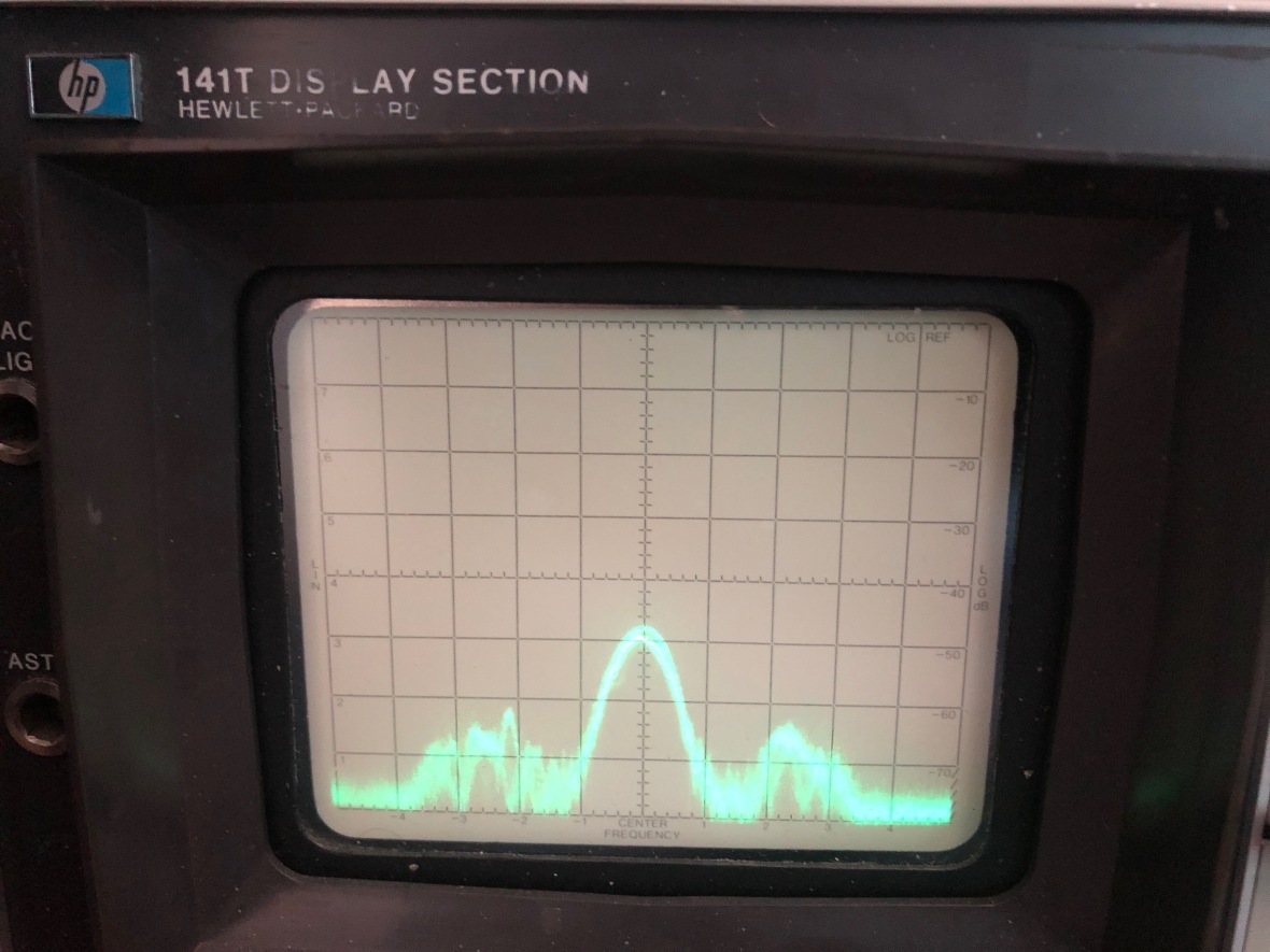
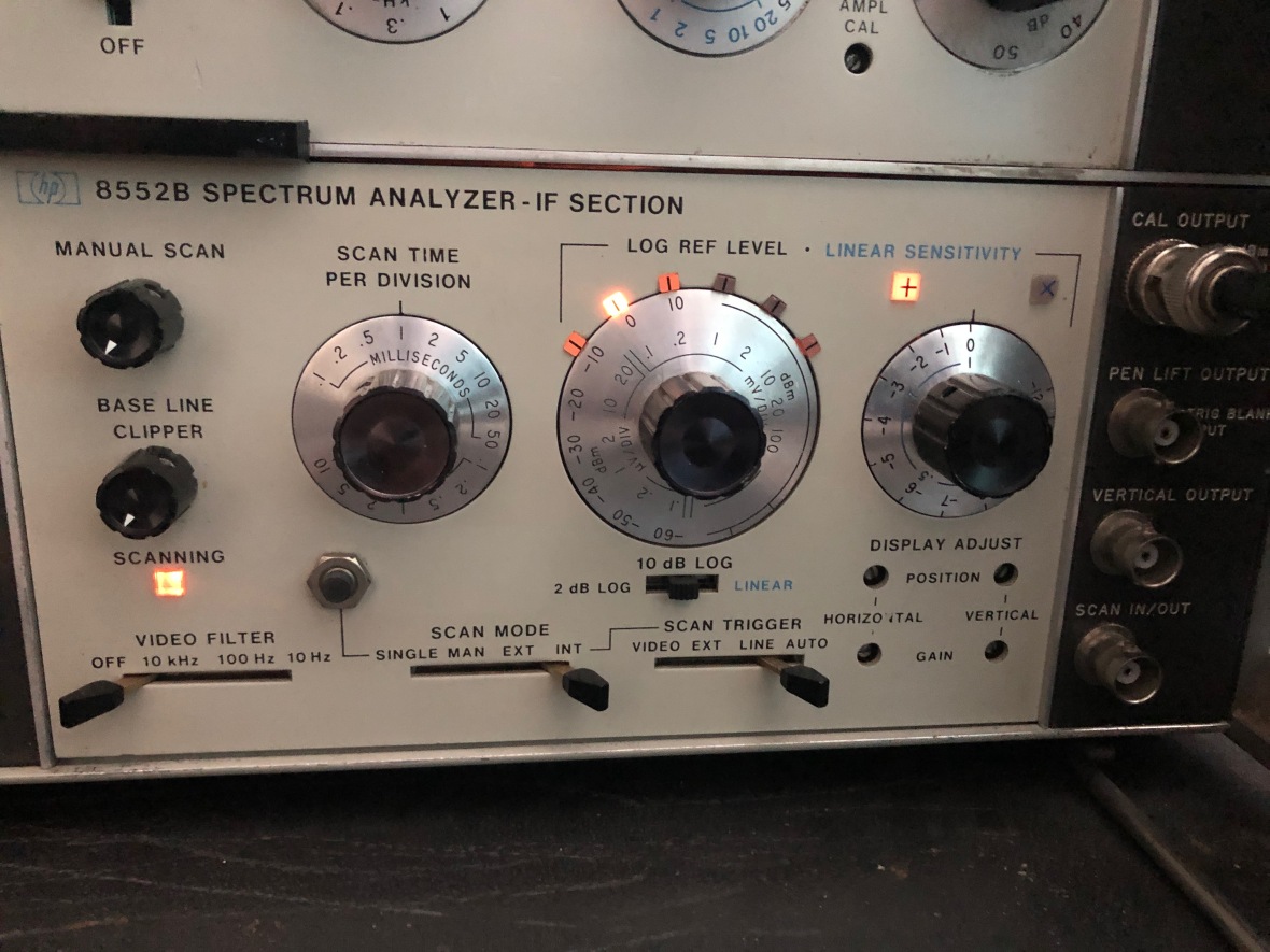
Problem #3 : Unable to set -10dB as reference level.
Extremely complicated problem. I was unable to set -10dB as the reference level. The way it works is the light across the rotary dial lits up to show that -10dB is the reference.
Problem was the bulb :). 28V miniature lamp. Replaced it and that is fixed too.
Problem #4 : Fuse blow in 8552B.
Okay this is genuinely serious. I was playing around and on one power up the unit is dead. No trace, few lights on, but nothing on screen. Swapped RF plug-in, same response.
Problem is with 8552B may be? Did preliminary checkup, found both the fuses at the back of 8552B for -12.6V rail are blown.
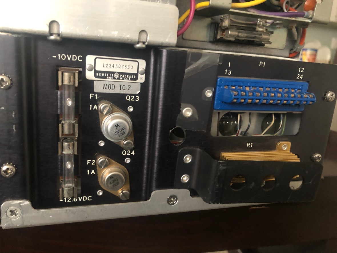
Checking the schematic for the 8552B shows why. SCR crowbar.
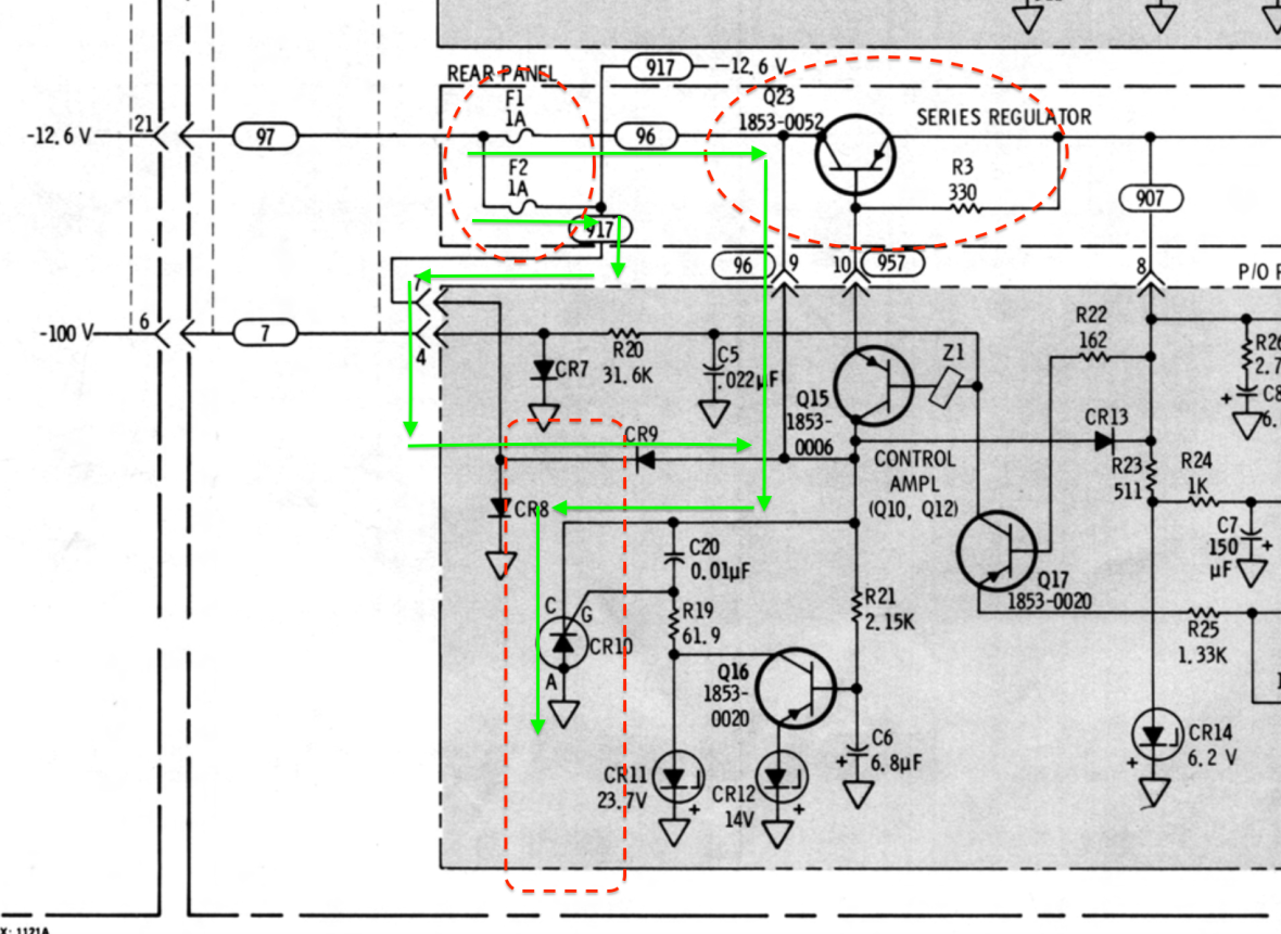
Replaced the fuse and it blew again after couple of power on/off cycles. Mostly during power on the voltages are going high that the SCR crowbar is kicking in.
Focus back to power supply.
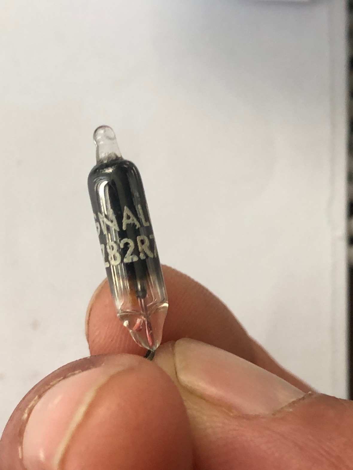
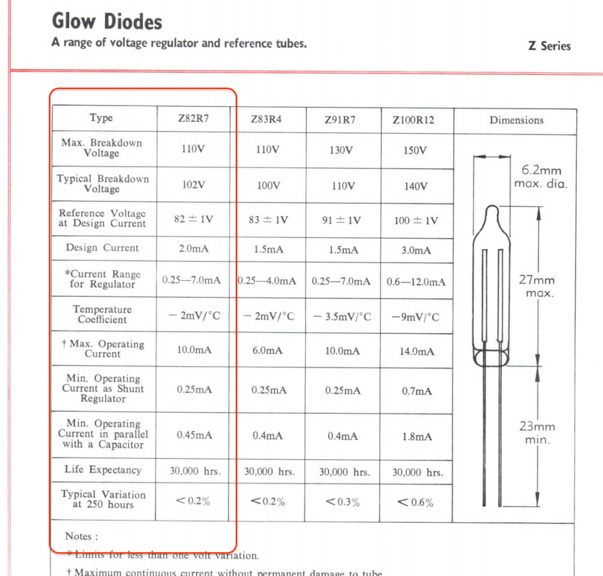
Here I discover one object I found cute but ignored in the power supply board, the VR tube, which is a neon here, A2V1 , Z82R7 with Krypton 85 stabilizer ;). This is the radio active stuff (oh yeah ) with ~ 10 year half life period. Reason could be as simple as the VR Tube, which is a neon is aging and takes higher voltage to kick start, causing the crowbar to trigger.
WARNING : RADIO ACTIVE MATERIAL, HANDLE SAFELY AS BELOW.
Jokes apart, I dont understand or have the know-how of how bad or serious or silly this stuff is, be careful and follow whatever precautions you think is safe and needed.
Decided to remove and test the tube to see the breakdown voltage. Here is there result from 576, with day light on the tube. 20V/div.
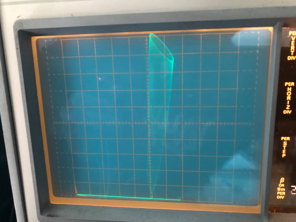 The ghost you see in the screen glare is me. Breakdown at ~ 140V and sustain at ~100V. way off.
I was able to dig out the datasheet of Z82R7 from internet and it says max breakdown at 110V.
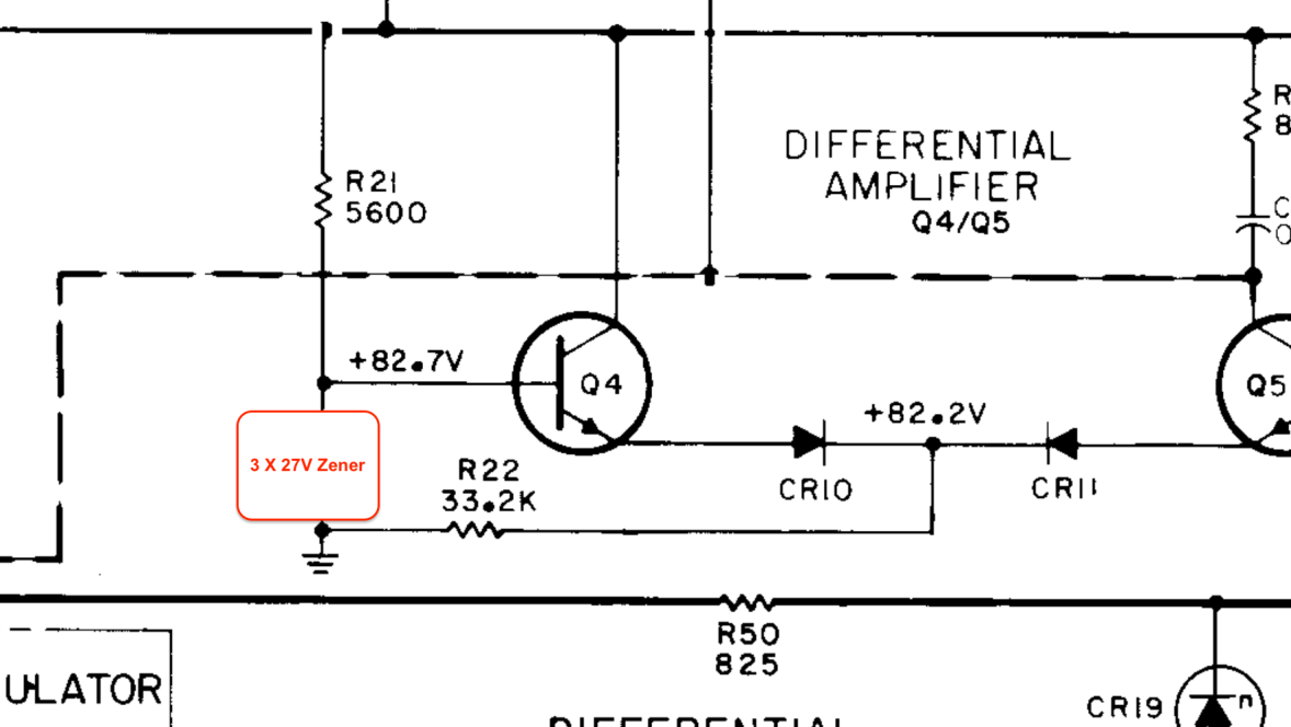
Now to the the modification, I decided to use 3 X 1N4750, 27V/1W Zener totaling to 81V.
And here it is on the board – Before and After


Time to test, as always wire up all rails slow power up via Variac. I wanted to see the voltage across the zener too, so hooked the zener also to the multi meter.
After about 15 minutes warm up, the Zener is holding at 83V.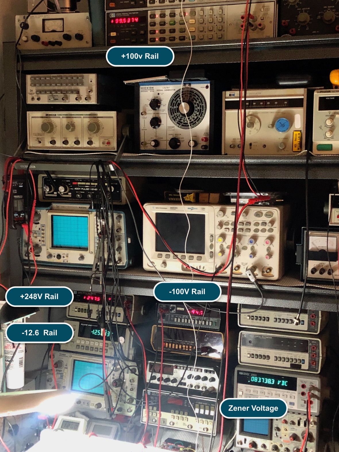
That brings an end to experiments with this instrument.
I have been using it for few days since then and all seems to be set for this.
Disclaimer
I have no commercial affiliation with any of the products/organizations/individuals mentioned in this blog.
The information provided here is for educational purpose only.
You are free to distribute this as long as it stays original with all information as is here and it is free and you don’t scavenge any tubes from any scopes or this blog.
NO electrons were harmed during the repair/filming of this instrument restoration. All free electrons found inside the unit were rehabilitated to the nearest vacuum tube.
NO EXTRA SCREWS OR PARTS WERE OFFICIALLY FOUND AFTER REASSEMBLY. UNOFFICIAL EXTRA ITEMS WERE DISPOSED OFF SECRETLY AND DECLARED AS “EXCESSIVE ASSEMBLY” DURING MANUFACTURE.
=== THE END ===

muy buena explicacion teno el mismo analizador de espectro hp141t una belleza
LikeLike
Gracias
LikeLike
Very nice I’m trying to learn it year in year out it’s really great materials.. still I don’t understand how such things works .
My greatest wish is that I will understand it .
I’m not high educated. Just a hobby but the willing is high .
Hours going fast to track down the faults .
Have the same analyzer
Working on the a2 low voltage part to get it up and running
A whole bunch of transistors are burnt .
Had to take the power section board out to test part by part
Q10 =2N3904
Q11= 2N3904
Q6 = 1854-0022 S17843
Q7= 2N3904
Q8= 2N3904
And a few resistors
R10 49.9k 1.0% ½ watt
R43 22.1k 1.0% ½ watt
Finding the parts..
#The resistors is also no problem have many vintage resistors here
#2N3904 is easy to find here had 25 so no problem
#1854-0022 S17843 seems to be a different story atlease it seems to be a common npn transistor only with a extreme low beta of 7 that says my component tester the breakdown voltage is 80v I could test it cause Q3 is also the S17843 and that one is good.
Have a few transistors here in the BF serie
Like BF186 with a beta of 49
Is that usable such of a transistor. Or no go?
Hope it’s no problem to ask it here.
Wish you all the best .
Raymond
LikeLike
Hey Raymomd,
The HP Part is available here for purchase –
https://www.sphere.bc.ca/test/hp-parts/hpparts4.html
It is a general purpose application, so dont think anything special in there, match the Max collector current, and max collector emitter. BF should work.
Since you have burned components, better check why it happened, so that you dont replace them and get fried again 🙂
LikeLike
Hi WELL I REALY ENJOYED AND SPIRTUALLY HUNGED ON YOUR BEUTIFUL DESCRIPTIONS AS REAPAIRING IS CONCERN. ME TO I HAVE A FEW HP ITEMS FOR REAPAIRING (I LOVE TO GET PRACTICING AND RUN MY BRAIN I CALL IT A good APORTUNITY FOR TRAINNIG OPTIONS TO PREVENTS ALTSHEIYMER ….. HI…HI…) SO LETS GET IN CLOSE TUCH WITH OUR BOTHE FUN IN TROUBLESHUTTING SOME OLD INSTRUMENTS) PLEASE LET ME KNOW HOW FAR U ARE FREE TO CONTACT WITH U AND DESCRIBE MY SPECTRUM ANALYZER’S PHENOMENA THANK U BEST REGARDS israel.
LikeLike
Thanks for the comment, let me know what are trying to troubleshoot, will be glad to look in to..
LikeLike
Just came across this. I have an HP 141T with the 12.6 v blowout problem as you described. I’ve been tearing my hair out trying to find a cause. Your discovery sounds right . I’ll look into this ASAP. Thanks for the clue.
LikeLike
In this forum:
https://forums.futura-sciences.com/electronique/903025-fonctionnement-dun-regulateur-de-tension-de-chez-hewlett-packard.html
We talked about the issue of blown fuses in the back of the HP8552B.
A simulation of the 10 V regulator circuit was made and showed that it would take at least a 1 KV spike on the -100 V rail to activate the crowbar. A -150 V spike won’t do it.
So the Z82R7 responsability seems unlikely.
We also talked about the reason why the -100 V rail is connected to the -10 V regulator.
This still remains a mystery,
Just as the reason of the two fuses in parallel instead of only one.
Some more talk about these topics in this forum:
https://www.abcelectronique.com/forum/showthread.php?t=103777
LikeLike
Thank you for the update Yuvan, I will check the discussion and point my blog to your link.
LikeLike