This is a 40 year old beauty. I love Tek for their amazing craftsmanship in designing, manufacturing this scope. I got two of these plus a cart for a decent price, in “as is” condition. So I have some work to do. First one, the M (Military Model) works well, without any issues.465M is totally modular unit, if you wonder how, check this video
This one, the regular 465 had a very strange issue.
Trace dsisappears once the unit is in use for a while. If you press “Beam find” it will come back and then again will disappear. Bit strange, but interesting. So decided to chase this.
Since its 40 year old scope, it needs a bit of TLC.
[Apologies for the poor quality of pictures, as all these experiments happen at late night after work, so will be dark, I will be tired to really take good pictures, even feel lazy to get the DSLR out, rather just click on phone]


The expanded wave form is the delayed trace on the 465. one of its key features.
Coming back to the problem, Tektronix 465 trace disappears. Need to press “Bean find” to get the trace back. it stays up for few seconds and again disappears. If I switch it off, and let it cool down, it all works fine for few minutes, once it heats up, again same issue. In between, I found the whole scope was switching off after few minutes of use. I observed its something mechanical as knocks or shakes on the chassis was putting trace back.
Googled showed typical issues, and very complex issues too, could not find solution to the problem I was facing. So decided to get inside and find and fix it out myself.
Lets first get this one naked and enjoy its beauty. As usual, these scopes are work of art, hand crafted piece of engineering or art I wonder. Here are some pics for you.


Important: These instruments contain high voltages on exposed traces. Be careful.
It can kill you as it contains live line voltage @ DC level directly on the board. Ensure you are skilled enough to do this.
Now coming specific to the issue of trace going blank after warmup. This is random, Pressing beam finder returns it for some time, again may disappear. Suspecting bad solder joints (common problem on these models), I re soldered all possible points. Still no luck.
Typical troubleshooting fashion, you start with schematic, trace block, section, function, and then component.
Follow the signal is the rule. Chase the signals from the deflection plate backwards so that you know where its failing. Or you can do the other way, follow signal from Input section and go all the way down the CRT deflection plates.
Did the same on both vertical and horizontal section of the scope, and my case, it was pointing to vertical stage, the signal was disappearing at vertical output board-
This is the small board kept inside the CRT Cage, bit difficult to access.

If you check there are components, with one leg on PCB and other one the special mount assembly for the output transistor, very complicated mechanical and electrical assembly.
Components literally stand up from the PCB to access the transistor mounted on the special heat sink.
All components looked good from outside. Still decided to pull it out.

This is how it looks once its out. All components tested good,
The real problem – ? a bad solder joint to the output transistor. The solder connection to one of the final output transistor was broken. The soldering was cracked, but still touching each other. So will work until the transistor gets hot, and then may get displaced causing random trace issues.
This is under the top portion of the board in the above picture. At the output transistor pins is where I had the broken solder joint.
Below pic shows the position of the board in the scope, next to CRT. I did a bit of rework and used flexible wires to connect the board to the transistor, (not ideal, but I wanted a safe option). Remember this cable can affect the output capacitance and ideal option is to keep it back to the factory style of connection.
If I recall correctly, some screws/mounting posts carry ground, so do not keep the board out and try to test. Also the output of this stage goes to CRT plate, so be cautious. Delay line terminates here soldered directly to the PCB, be gentle on that too. Not a modern connector, be careful.

My scope was all good after this. I knew it was something silly, and it turned out to be so.
Few observations and tips based on my experience
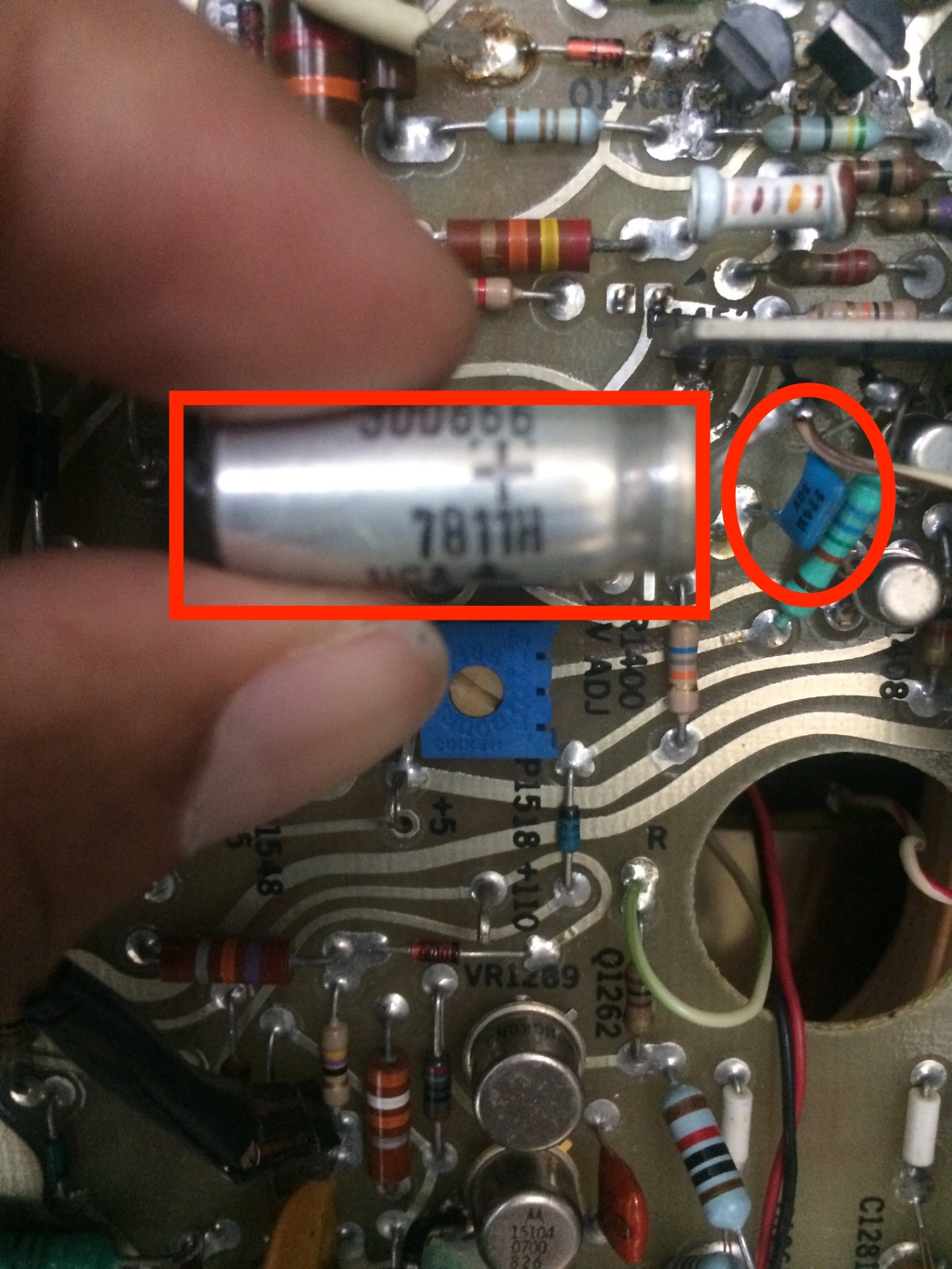
- These generation scopes and plug-in Modules are well known for shorted Tantalum capacitors. They go dead short and can bring power rails down. The power supply has foldback protection, so it will not come up if there is a short in any of rail.
- Typical symptom of this is – no power, or powers up and shuts down, or powers down after a while -> reason – shorted Tantalum cap in one of the power rails.
- After powering off the scope and ensuring all rail voltages are zero, check each rail for short using ohm mode of your multi meter. The tantalum caps are all over the place, on main board, trigger, vertical/trigger boards, you may need to hunt down the bad one.
- One of the trick I use is to get my 6.5 digit HP DMM to trace the bad cap. Keep the ohm readings high resolution @ 6.5 digit, so that as you get close to the shorted cap/trace, the resistance goes down.
- You can replace the tantalum with modern electrolytic, remember the polarity, in electrolytic or even if you are getting a tantalum replacement.
- Silly, still remember, there are -ve rails, do not just recap filter capacitors by making -ve of the capacitor to ground.For -ve power rails, the ground is +ve terminal of the cap.
- If you are lucky, some cases bad caps can visually be identified, as they get hot and change color slightly.
- Check my 475A and 5110 Repair pages for examples such capacitor failures.
- Power supply have fold over protection, so in case output is low or not there, check for shorts, caps, than suspecting Power supply.
- Bit of a no so ideal cabling, Few examples below.

- These are shielded cables, running close to regulator transistor heatsink. Even a tiny scar on their insulation can expose the shield ground wire inside. Whatever it touches, it can short circuit. Do check if they are causing shorts due to broken insulation
- Transistors are seated in a conductive foam sockets, not soldered. They can come off during cleaning, transportation, or even by mistake when you work on something near them. Visual inspection of all transistors around the area of trouble or area which servers the signal in question can help a lot.
- Line voltage, fuse, DC all directly on PCB, exposed. Be careful. All the power supply TPs are near this box. TAKE CARE

- All the power supply filter caps are on the other side of PCB on the marked section.
- Power supply ripple. Bad electrolytic in the power supplies can cause high ripple and totally random traces. Always good to check power supply ripple is within the specs and replace bad filters if needed.

- Before removing any PCB, remember to de-solder connections to BNC connectors :). Coupling caps literally carry signals by standing up on the PCB


(sorry bad picture)
- Remember, again not just electrolytic, Tantalum too.
- Last but not least, don’t forget the wires which are directly soldered to PCB. They are equally vulnerable to mechanical stress – if some one wild was inside.

Exceptional service manual from TEK as always. All DC voltage levels are marked in it, for you to check, so do waveforms. Thats all for this, here is the scope, I have been using it for almost an year after the repair for hours, and no signs of any trouble.


Please do notify me me in case of any technical errors in this document – Thank you.
Back to Home Page for More Crazy Stuff

I have a Tektronix 7633 with no display. I need to get a HV Probe to check the CRT supply.
They sure improve their looks with a good wash and polish!
LikeLike
7633 is a monster, congrats. While waiting to get HV Probe, you can check if the HV oscillator is working on its LV Side.
LikeLike
Nice thoughtful tips.
LikeLike
where can i get service manual pages with voltages??? That would be so nice for myTektronix 465
LikeLike
google for Tekwiki, you can find all details there
LikeLike
I saw that you are in San Jose is this correct? Do you have source for new parts, particularly cases? I have a 465m that my wife stacked some stuff on top of in a closet and cracked the case breaking a chunk off and also the front cover. It was working before that but would love to get it a once over to make sure still within spec and nothing was broken inside when the case cracked. I have not powered it on but am in the process of building a garage shop and want to add it to my workbench. Thanks
LikeLike
Case – Sorry no. You can try excess solutions for other generic parts.
LikeLike