This is the story of my affair with Vacuum Tubes, and Tektronix.
I came across this 549 which was neglected, and thrown in a corner of a dirty garage, and the owner was selling this, as they wanted to get rid of it. Seller had no clue what the hell this damn heavy box was, all he knew was he can not ebay it as shipping will be more expensive than actual cost.


I was able to bring it back to life, after may be after 50 years it was born. Elder than me, so with all due respect, this is how this scope is now in my Lab 🙂

It took me exactly 3 months, consuming almost all the weekends, Christmas holidays, and countless late nights. I do have a day time job which is no way directly connected to electronics, rather more computers, so all the pictures you will see here will be dark, as most of the work on this happened in the late night, after work and dinner.
I am not a guy who worked on Tubes much, studied it just in two pages as it was all transistors and VLSIs by the time I was in college. But I love tubes, all hand-made, I believe they contain passion and commitment of the person who assembled them, they have the “human” Touch. They are organic 😉
If any tube guru is reading this and find an error, please correct me, as I may be wrong with some of my assumptions or understanding.
Here is a video of the whole circus, which I recorded in 2019. The original restoration was done in 2017.
Update: May 16, 2020
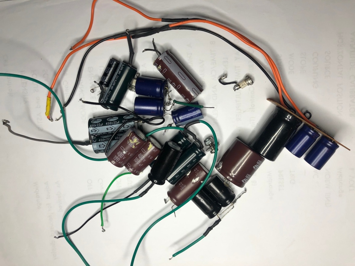
I decided to “Uncap” this instrument. Well what I meant by that is to remove all the ugly electrolytic caps and reform the originals.
In that process I also produced a video explaining the storage operation.
Here is what I took out of the instrument.
Detailed pics at Tekwiki – http://w140.com/tekwiki/wiki/549
And here is the video.
Quick Bio of Tek 549
CRT Storage Oscilloscope- Yes, you store the waveform in CRT.
59 Vacuum Tubes – Tons of 6DJ8 dual tridoes, and 2nd largest count is 6AU6 pentode. No wonder Tube scavengers are after these.
35 Transistors
13 x 17 x 24 inch / 330 x 432 x 610 mm
Power consumption – 650W, 750 VA
Weight -31 Kg or 68lb (!!!!!)
Tube+Transistor Hybrid and brilliant design. Best quality components. Definitely bunch of Tek Custom components, on the high speed diodes, custom value resistors, above all the storage Tube.
Acknowledgments :
To the great men and women in Tektronix who designed, manufactured rather handcrafted this engineering marvel.
To my friend Kris, who gifted me my FIRST Soldering station – of my life – Note: I am soldering since I was like 11 years old and never had a proper soldering station, even I wonder why !!
Laura, for gifting me a lot of her Dad’s Toys, which were very instrumental in making this project a success.
Paul of Mr.Calsons Lab, for contaminating my brain with Vacuum Tubes and making me do this with the knowledge and passion he shares through his channel
Note: I am not going to explain the details already covered in other websites or service manuals. I will cover only the missing parts or stuff which needs clarification to make it easy for someone who is attempting something similar.
So here is the whole story. This was the condition when I got it.


")


No Doubt, Step #1. Clean . Two reasons for cleaning it, first, considering the condition it is in, its not “electricity worthy”, second, there could be foreign objects inside this, could be even animals, or dinosaurs who knows.
Tools you need for this : –
1. Gneric screwdrivers
2. Inch spec HEX keys are needed for removing the knobs. WARNING : Tek uses/used inch size Keys in these(not metric aka MM). If you attempt to remove the knobs using standard MM Hex keys, you might end up ruining the knob, I used the below one from amazon.

2. A very Strong table to Keep this heavy boy. Remember its 31Kg or ~70lb. One of my study table was bend after keeping this one for few weeks on it. !
SAFETY WARNING
- Two people are recommended to lift this scope. I mean it, else be prepared to hurt your back, or drop it and crush your foot.
- Do not remove the side covers and move them around. The Vertical AMP Tubes are exposed without any protection. If you hit them while moving around, you are fried.
So here is how the vintage beauty was given a complete clean up
Panel – Before and After


You can find the amount of dust in the rear panel here, the right corner is cleaned

Rear Fan and Fan Grill, Power Connectors, Fuse


Front Panel and Knobs


Now lets move to the inside.
Here is the process I followed
1. Clean/Inspect every part/item/space
2. Clean every Tube, Inspect the Tube Visually for Leak (will show you what this means later in a pic)
3. Clean every tube socket
4. Same for Transistors, and their sockets.
5. Visually inspect every component as you clean.
6. Look for foreign objects, parts, screws lying around and could cause short circuit
Here it is all in pictures
Special Tools :
1. Air compressor to clean the internals. Makes your life easy 🙂
2. Alcohol – to drink and clean.
3. Patience, a lot of it.
4. Good eyesight -> yes, need to literally inspect every part very carefully
5.Microfiber cloth. to clean the Tubes -> CAREFUL – DO NOT WIPE OUT MARKING on the tube
IMPORTANT : DO NOT SWAP TUBES EXCEPT FOR TESTING. KEEP ALL THE WORKING TUBES IN ITS ORIGINAL SOCKET/POSITION IN CIRCUIT
REASON – IT MAKE CALIBRATION PAINFUL IF YOU SWAP TUBES AROUND RANDOMLY.

Here you go, all what I wrote in action –
Remember. Do not remove more than one tube at a time. Do not wipe off the marking on the tube. Do inspect the socket for broken pins stuck inside.
Lets start with the the Plug-in.


Now inside the scope – First Vertical AMP. These 8608s are not protected and exposed directly on the side. Reason is to keep them next to the CRT deflection plates. Be careful while keeping the scope without clothes(side cover) as these tubes are vulnerable , do safeguard these beauties when you work on the scope.


Now to Timebase B/Delay trig Chassis (the “Tube Door you open on the side) and Low voltage Power supply.


and main Time Base A, Horizontal Amp and HV Power.


and Here is the new tool – Chopstick Cleaner !!

Here are the hidden treasures inside the scope. You will understand why I was insisting on “inspecting+Cleaning” when you see this –


First , a screw fell off the house to this scope – deep inside the tube, almost next to deflection plate connector (Horizontal) , which means it was sitting without covers somewhere. Second one is the thrust washer for a POT/Switch, may be left inside by someone who replaced a front panel component. Remember, front panel pots carry -150V to +100 or more, so a short there is also dangerous.
Now, few Tubes are Hidden/not so easy to find/Spot. One of them is the Thermal delay tube . This is used to warm up the tubes before applying plate voltage. Second the Horizontal driver and HV Transformer Driver Tube – a Beam Pentode.
You may be totally lost where these things are, don’t worry, I will do a total survey of the scope later, which will make it clear, for the time being enjoy this Porn if you like it 🙂


Causalities from the Preliminary inspection


This is the visual inspection of the Tubes I was mentioning earlier. Check for white smoked Tubes. This is an indication of Leak/Air inside the tube. Some tubes may be cracked and will break apart when you try to pull it out. Not to mention be gentle. The first fella who was leaky is an important Tube, its the all popular VR aka “zener” Tube 5651. Second fella is a 6AU6 from LV Power supply (Funny, Low Voltage Power supply Means – very low voltage of -150 v to +500V).
Few more Observations, Exposed high voltage (low voltage haha ) conductors, possibly can short critical components, this was the first fix I applied. The purple wire in the picture is my replacement . This is the rear side of the chassis, near the CRT Grid/Cathode Switch and Remote Control Connector


They can short circuit themselves to the ground plate and make our life really sad.
If you read through the entire project, you will realize, this was the root cause behind all the trouble.
Now lets get to Part II of the game. Real troubleshooting and Repair/Restore.
Before we proceed
::SAFETY FIRST ::
DO NOT ATTEMPT TO REPAIR/OPEN/OPERATE THESE KINDA DEVICES UNLESS YOU REALLY KNOW WHAT YOU ARE GETTING IN TO. THERE ARE DEADLY VOLTAGES EVERYWHERE AND IT CAN KILL YOU. THERE ARE BETTER WAYS TO DIE IF YOU ARE UP TO THAT.
Even if you are familiar with electronics, be very careful when you work on something like this. Here is the voltage map on the top side of the scope. Specially note the unprotected -3700V. Do not poke around with multi-meter or scope probes without verifying (thrice) the point you are checking.
Use instruments with right attenuation probes, example, 10:1 probes or HV Probes, else the instrument can short circuit the scope circuits, damaging both.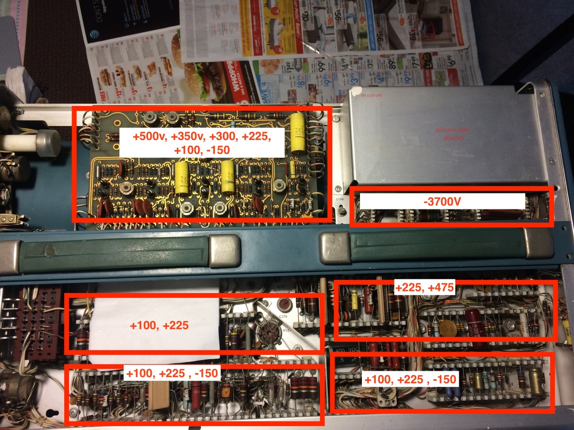
Similar Voltages are all around the scope.
Front Panel BNC connectors for Trig, Gate+ etc are around 20-40V and Sweep A can go up to 180V. Do not fiddle around with these either. Calibration out voltage can be set up to 100V watch the rotary switch before using CAL OUT
(don’t be excited that it was showing a trace, I took this picture midway during restoration, you can see the trace is not liner)

To Proceed with restoring this, I had to follow a clear plan, to ensure I don’t kill myself or the scope.
- Service Manual, Tek Reference Documents – Concept Series [ MUST if you want understand the tube circuits] – What an amazing website @ http://w140.com/tekwiki/wiki/Main_Page
- Basic Check all the Tubes -> Tube Tester or if not possible with basic multi meter -Painful as you have ~ 59Tubes in side.
- Capacitors – This is not a vintage radio where you can find paper caps and you replace them and get it working, NO !!. This is highe end test equipment crafted by Tek and used the best quality components. However the main filter electrolytics, I will not trust them, rather replace. so, Check caps generally, replace all electrolytic, check the condition of Mica/film randomly, Trust discs caps unless they prove otherwise. (Sorry too many, way too many caps to check all, and hard to access too)
- Disconnect all sections from transformer secondary – except Heater and fire up all tube heaters in steps. I will not do this straight , rather will be gentle with Variac.
- Power up low voltage power supply (yeah the +500v kinda low voltage) step by step and section by section, monitor, check, smell..again gentle with variac
- Once confident that all good, go ahead with full power and start testing each section by section, find more faults, repair until its all done
- Calibrate
So, lets start with some of the tools – again only special tools – which are good to have to make your life easy.
1. Of course Multi-meters, but how many – aha, prefer 3 minimum may be 4, Will tell you why. Minimum 2
2. Variac which can handle a 650W/750VA Load and provide Isolation if possible.

Note: The yellow liquid you see above is the chemical enhancer used to smooth the flow of electrons 😀
Jokes apart, do not consume alcohol while working on any stuff. This was photo was taken end of the troubleshooting session of the day, while relaxing, NOT “During” troubleshooting. Never drink and work.
3. Tube Tester – Easy to test tubes. We need to test tubes for Short/Leakage (Not gas leak, electric leak between electrodes) – You can manually test the tubes for short with Multi-meter, but trust me its pain as you need to look up pin-out for each tube.
and Most important, it can tell you if the tube has got right Gm. Very important and saves a lot of time.

3. Transistor Tester – Component Tester

4. Silver Solder – This generation of Tek scopes uses ceramic strips to hold the components, with connectors bonded to the strip. Another Tek innovation, and hey need solder with at least 3-5% silver. Remember don’t buy anything which says silver solder, it should have 3-4% Ag – You can google for reasons to use this solder.

5. Cap Tester -> Modern to check value and Vintage to test for leaks. Check my post on the restoration of this EICO 950B in case you need more details


6. Oscilloscope and 1:10 (HV) Probes. Prefer scope which is not grounded – Like the tiny little Tek I used. I have used my Tek 465M too whenever I wanted dual trace during troubleshooting.


7. HV Probe for Multi-meter – Needed to check HV Section – I used my VTVM with the HV Probe. I dont trust a DMM there, rather prefer VTVM.
[Warning : VTVMs have -ve Probe grounded to their body, be CAREFUL]


8. Function generator – Saw-tooth output is handy, as for scope that is the wave you need the most. No need of high frequency output, max 2Mhz will be good.

Of course you may or may not have all of this, but a creative mind can find out alternatives. So don’t be disappointed if you don’t any the toys above.
Lets start Setp1. Test all tubes. Lets test the first suspect we have, the VR Tube.
Here you go, it is indeed leaky, instead breaking down at 85-87, its is holding on till 118V.

I was a bit suspicious about the tube tester, as its 40+ years old too, So I checked the Voltage he is applying against the tube and here is the result,

Here it is, against the Fluke Bench Meter 5.5 Digit ! Amazed by the accuracy of this 40+ year old gear. Thank you Laura again !
Time for shopping, I was expecting not to replace all the caps, still got some inventory on-board. The usual trip to HSC (http://www.halted.com/) and here is the shopping bag –

Now lets focus on the Tek 549 Power Supply.
The basic design is a transformer to rectifier Diodes and then hits regulator section. There are numerous output voltages as outlined in the service manual. All refer to -150V for reference, which is stabilized via the VR Tube. They also cascade stages to get higher output without having extra winding on the secondary.
As identified earlier, will replace 5651 first. Here it is in the schematic
[12AX7 as bridge -;) ]

I replaced the broken 6AU6 as well. Now time to tag and remove all the secondary lines, rather all Lines EXCEPT Heater. I tagged every wire from the transformer and removed it, so that only heaters stay on. Removed plug-in.


Now time to wire the unit to Variac and Power it up, for the first time.
Slowly increased the variac to make the fan spin slowly, and tubes glow. Remember, not all tubes will glow without Plug-in. I stopped variac at 60V which 50% of the rated line voltage.
This was the most dangerous step #1. Transformer is taking power after years, so do tubes, cables, I applied 20V Input first, then slowly increased input in very low increments of 5 V, waiting and checking everything for 5 minutes before next increment.
Time to check the voltage on all the heater lines and confirm its ~3v-3.1. Check for all tubes for the sign of heater glow, smoke. This is to ensure that we don’t blast the heater with full voltage after years being idle. Since the input is only 50%, so do heater voltage 6.3V/2.
Here is the beauty shining after years. Remember, keep your eyes and ears and NOSE open, for burning smell, hum, to ensure that all is good 😉


remember, 5651 is like a neon, it don’t have filament, ( side note : if you work on tube gear 1v2 diode does have a filament, but cant see it glowing as its only 1v filament )
I kept it on at 60V for few minutes, confirmed all is good and then pumped up the voltage to 115v. All went good. All tubes except the ones hair-pinned via the plug-in were glowing. Warmed up the unit really well. Remember, there is no other power active in the unit, only heater.
WARNING
REMOVE THE TIME DELAY TUBE FROM THE OSCILLOSCOPE IF YOU ARE PLANNING TO KEEP THE SCOPE POWERED UP WITH JUST HEATER POWER FOR EXTENDED TIME . THE TIME DELAY TUBE HEATING ELEMENT IS DESIGNED TO BE ON ONLY FOR 50-60 SECONDS AND CUTS ITSELF OFF AFTER THAT. IF YOU APPLY JUST HEATER POWER, THE RELAY CAN NOT CUT THE DELAY TUBE OFF.
Next step – Capacitor Replacement.
One thing for sure is that we need to replace all Electrolytic Filter Caps. Disc Caps, will leave as it is. The second category of caps I see is the Film. I was not sure if it is paper or not, as in the service manual its mentioned as Paper. If it is paper, I have to change all.
I removed few and tested with my EICO 950B and all of them were good and not leaking.
For those who are not familiar with Capacitance Leak tester, here is how a good (left) and a bad (leaking) Cap shows up. Read my post on EICO or Heathkit C-3 in case you wanna know more


These are the two kinda of Caps I found in the scope, other than Electrolytic and Disc


I was sure they are not paper, still wanted to confirm, and there is only one way, the easy way ! 🙂


This is what is I call as Confidence Building Measure :). I was more confident to proceed and leave these caps as it is. Remember, they could still be one or two who are bad.
NOTE: Ensure the Mica/Paper Types Caps (in Service manual parts list, shown as as type PTM) are NOT leaking. In some models like initial batch of 535/RM35s I saw a bunch of bumblebee caps, every one of them was leaking, including the Caps used in HV Section. Do not assume the caps are good, do test them randomly and replace all if you find any leaking.
Now Time to replace all electrolytic. I was not sure if I can really bring this guy back to life, as I still don’t know the condition of CRT, main tubes. So decided to do a bad job of “Temporary mounting” the caps. I didn’t want to remove the original multi-caps to keep the unit looking original. Sorry for the really bad job, but it was only temporary, used Nichicon caps all over. There are so many over all the power supply rails and different Decoupling stages.
Tip: The caps are expensive – Easy option – Scavenge from “Good Quality ” SMPS if you can. People throw them out all over. Do not use way too high value than what is in the original design (do not use 100uf 450v instead of 20uf 450v as it can load the regulator tube while initial charging)


Apologies again for the bad job, but it was only temporary to test. I did proper mount of all these caps after finishing the restore. At this point in time, I was still crossing my fingers.

Ever wonder why some caps have the plastic shield on them and some of them dont ? Well they are for protection. Remember, they cascade power supply rails to get high voltages. So + of one power supply rail is used to bias/raise the -ve of 2nd. Which means -ve rail of the 2nd Power Supply – where the filter caps sits – will be carrying +v of the first stage. Since the outer shield is negative for these caps, they shield them with these plastic caps to ensure no one accidentally touches their body and get RIPed. DO NOT REMOVE THESE COVERS.
Now the main event starts, powering up. There is a bit of trick around the whole powering up.
This unit is well designed to protect its tubes. So it does not apply Plate voltage to the tubes in one go. They first turn on heater supply, make the tubes warm up, then only apply plate voltage ~ after 60 seconds on a cold start. This is to extend the tubes life and protect their cathode (google for more details). They use a thermal delay Tube to do this.

This tube, drives a Relay, which switches on all the power output after the time delay.
This tube is near the Vertical section, hidden under the chassis, hard to reach) Relay is next to it. IMPOSSIBLE to reach -:)

Lets see this guy in action –
As shown in the below pic, during OFF State, this is how the switch inside the tube Looks like. You can see the gap between the contacts.

Below pic is taken after warming the tube up, This is how it turns ON after a “Thermal Delay” or after the filament in the tube is warm. You can see the plates closed, making the contact ON

Here are two videos explaining the action. Its taken from a 535A (RM35A) and 547, but the concepts remain the same, just the part# is slightly different.
Video-#1 – Whole concept of Time delay for Plate Voltage
–Video–#2 – The Time Delay Tube in action
This is a very nice feature, but challenge for troubleshooting is, you can not do the mild way of applying the voltage slowly. Second issue, the relay is driven by the +100V Rail. So you need to bring up +100, and -150v together at the minimum to get started.
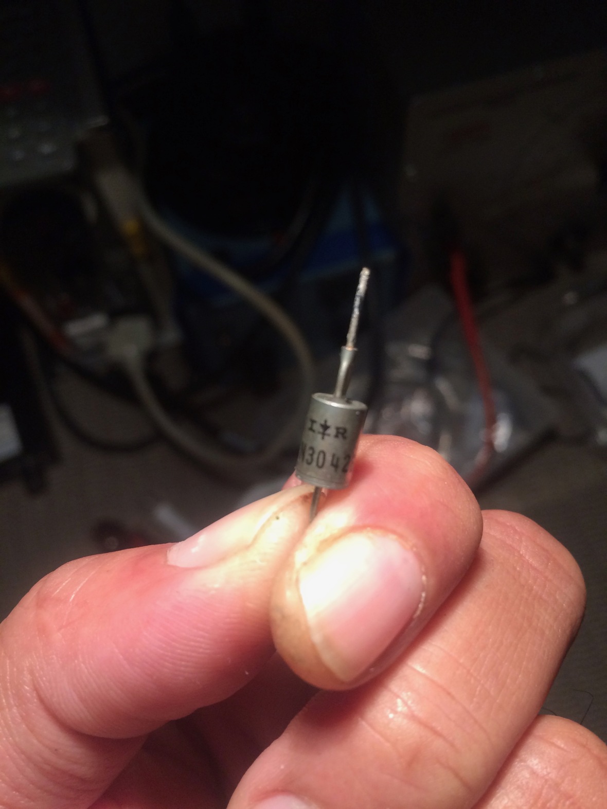
Before that, we need to check all Diodes, for the rectification. Here they are in the chassis, so do the location of the relay contacts. They are behind Time base B door.
On Power supply, -150V is the reference. Which is used to regulate rest all power rails. So -150V has to be first. So I re-connected the +150V secondary from the transformer, secondary no 19 & 20. Connected multi meter to 150V Rail. Then connected +100V – 21 and 22 – of secondary. Connected multi-meter to 100v rail too.

Again via variac, slowly increased power. Another multi-meter to watch AC input. If the input voltage is too low, thermal delay will not trigger, as the delay tube will not get hot. So it clicks around 75V input *AC* to the scope, after a 40 second delay. You need to watch and smell carefully here.
Well, just a pause, I had to go with 3 multi meter here, one for AC input, 2 for DC Rails, to watch both rails are following in the same ratio. Now you know why I mentioned multiple multi meters.
[I know some folks prefer the smoke test, like how Louis Rossmann does with Mac Book Board on 3.3v and 5v rails. I do not prefer that personally, as here the voltages are 100s and 500vs , and the damages will be severe in case if its a dead short somewhere]
both rails were showing relatively (to input and to each other) good voltage, as you increase input, the VR Tube will trigger, and watched the voltage output of -150V rail. ~ 100 V AC In, I was getting -150V DC. Test the regulation, by adjusting power supply adjustment resistor R616 which is basically the -150V adjustment. See the above Pic. Ensure the voltage is varying with R616, stable once set, no smoke, and fire.
If you adjust -150 on R616 it should change +100V rail along.
If you are still alive, and your house is standing in the same place it was before, and is not black in color, and you don’t see any red trucks around with bells and whistles, Congratulations !!!, its all good. You did not set the neighborhood on fire with your scope and both +100, and -150V rails are good. There is no overload, short in both rails.
In case you observe that any rail is loaded, stop and investigate, else it can kill the regulator Tubes. That is why its important to run input as low as possible to and get the relay clicked.
I followed the same steps by connecting each secondary winding, one after another like +225, +300, +350 and +500 and +475, until all rails were good up and running. In each stage I did not keep the scope on for more than 15-20 seconds, to ensure that nothing is overheating or circuits are sitting with partial input voltages. After powering up each rail I checked the entire chassis to see nothing is overheating,
here is how my bench was looking at this stage – with meters monitoring all main power rails, door open for me to run out in case of explosion 😀

This was a flat “–” table, after keeping the scope for few days it became a “U” table. I was worried it will become a W or N table, so I decided to offload the scope to a bigger piece of Rock.
All the power rails were good, Now what ? What is on the display ?
There is hope, I see a dot. No trace ! . Time base A is dead, Time base B. working but unstable. Sweep is short.

and disaster, one resistor on Timebase A is burning HOT – R136 of Schmitt trigger ! And its its the sweep gating multi, that is dead. Power off !!
This is the reason I mentioned to power it on for only 15-20 seconds in each step, to check all components for heating, to catch an overheating part before it burns out.
Checked voltages around the sections with reference in the schematic, and the R136 was seeing +45 instead of being in -30 to -47 range. I do see serious trouble. Started chasing the reason behind it. Found two tubes faulty in Time Base A – Miller Run-up V161 – 6CL6 is leaky. V183 – 6DJ8 for Hold-off and Unblanking is dead short.
I had ordered a bunch of 6DJ8s *expensive* due to audio folks looking for matching triodes.
NOTE: Do not order matching pair, you dont need matching pair in this scope other than in one or two places.
Stupid enough, replaced both tubes, Not much improvement. This is confusing. I started chasing everything, checking voltages around, no improvement.
DO NOT REMOVE THE TUBES AND TEST THE SCOPE TIMEBASE. THESE ARE CLOCKING/SWITCHING OSCILLATORS, IF YOU REMOVE ONE TUBE, IT MAY/CAN DRIVE THE PLATE OUTPUT TO B+, WHICH WILL BE COUPLED TO THE NEXT SECTION GRID TO FULL B+ AND THAT TUBE TO FULL ON STATE AND CAN FRY IT OR FRY THE PLATE RESISTOR (OR CATHODE RESISTOR IF ITS A CATHODE FOLLOWER) – IF LEFT ON FOR TOO LONG.
Time base B is still working, but A is dead, just spot. All voltages around Gating Multi was weird. I started removing Tubes around for quick check and found V183, the hold on circuit + UNBLANKING Tube was causing trouble. Checked that tube again, and wow..the replacement tube is also Burned !
So here is the lesson, if you have tube which is burned (shorted), DO NOT just replace. Always check why. On a multi element tube like 6DJ8, always confirm which section is actually burned. its a Dual triode. Pulled V183 out, and verified, to my shocking surprise, the V183B – Unblanking Section is Shorted !!! (my stupid brain was suspecting issue with hold-off circuit or miller run-up CF and disconnect Diode).
How to check which section is really shorted in a multi element Tube like 6DJ8 ? Use multimeter, and see which pins are short, and see which triode they belong to and match the shorted Pin # in the schematic.
I decided to stop and test all Tubes in the scope. Literally every tube was tested. Almost all were good, except one or two which were leaky (~5Mohm Leak). Replaced the leaky ones. Few were with low Gm – 6DJ8s. Being a switching device, I kinda let them be there, except two which were totally low, which I replaced.
DO NOT SWAP Tubes randomly. Also if you need Spare 6DJ8s, to try use it from External Horizontal AMP V314. Rob Cal Voltage Generator V875 in case you need a 6AU6.
Back to Track, why Unblanking Section of V183 is failing. I traced the unblanking pulse, which goes to time base selector (Horizontal Selector) switch and to Horizontal Section.
and here is the “Root” Cause.

The Symptom – R136 Overheating,

Caused by V183 getting Shorted…
Which is caused by a DEAD short Zerner in the Horizontal Section. D844, 82V Zener was dead short. 
The point marked as -42 was reading +42. So now the story was clear. This diode was killing the Unblanking Triode via the Horizontal selector switch, which was killing Trigger Gating Multi, which was killing Time base A.
Well, This is a disaster, things needs to be worse. This scope is literally a component Jungle, layers and layers of components stacked one on top of another. I started removing the top layer resistors around V183 and here are the blood stains 🙂


The plate resistor of cathode follower V183B is burned SHOT !!! R187. You can see how difficult it is to trace this out, impossible to visually inspect from outside.
Note: I put a X mark around the ceramic strip to locate where the component lead was removed.
WARNING: after soldering, WIPE OFF THE FLEX with IP. Else after/during power up, the terminals can arc via flex due to high voltages involved.
Here is the culprit !! who caused this trouble – D844 – in the Horizontal Section (Physically located towards the rear of the chassis on Top. Near Remote control connector side.
Time again to run to HSC. Second, this is a serious issue, How come Time Base B was working. How come it survived. Since I burned by bum once with one Tube, I am being careful. Decided to dig deep in to Time Base B. Spend many hours..no trouble at all there.
No WAY !!!. This should cause some damage there. Nope I am disappointed. All looks good in Timebase B. Time Base B is the Tube Door you open on the right side on the scope.
Replaced V183 Again. Replaced D844 zener. The 27K 2W resistor next to it, R845, was getting too hot earlier, now its cool and calm. In the Pic below, I kept the faulty zener next to new one.

AND SWEEP A Works -:). !!!! ..well..yeah works..just works 😦 not the way I want 😦

two issues. Both Time Base are Non Linear. Second, When I switch Positions, time base A vertically jumps off screen. Need to position it manually every time I change Time Base from A to B and vice Versa.
PLUS the original doubt, of why Time Base B was working and didn’t burn out. I also observed, Time Base B trace is a bit weak (Less Intensity)
Lets attack the easy one first. I monitored the voltage @ cathode of D844. It should be between 35-95 as per schematic. I switched between time base A and B, and the voltage I see on time Base B is very low. Definitely something IS wrong there. Time to enter the Jungle behind the ceramic strip.
Here you go, on time base B, the shorted Zener burned the Power Supply Resistor R200, 47Ohm – which is supplying +225 to V293, the unblanking Triode for Timebase B. V293 was all good since the resistor took the hit. Here is the Raid and arrest pictures.


The interesting part is, since there are two layers of components, its hard to find a burned resistor underneath the top layer. You have to lift up the top layer to see what is going on underneath.
Here is the path of the failure in time base B schematic.

Now next problem. Time Base A again, was drifting away in screen compared to Time base B. This was simple, the clamping Diode in Time Base A Gating Multi was bad. Replaced that with a closest Germanium Signal Diode D129.

Now, both sweeps are good. Stable, working in auto and normal Trigger. Sweeps are good.
Now time to attack the Sweep linearity issue. Here is the symptom. Both sweep non linear. Initially I thought it is a calibration issue. Fiddled around with all calibration POTs as I was lazy to troubleshoot.
This scope is to testing me -:)
So decided to fix it next in proper manner. Here is the thought line.
Check Time Base A out signal for linearity – on another Scope
Check Time Base B out signal for linearity – on another Scope
— Both sweeps are Linear
WARNING: USE 10:1 Probe | High Voltage Probe to test waveforms from this 549. Else it can burn the scope you are using to test this, or can burn the power supply in this scope. Ideally a battery operated Floating Scope (no ground connection) with 10:1 Probe rated for 400V or Above is recommended.
Next step –
Check the AMP output in another scope – Non Linear, hence the Trace is non linear.


That points the problem to Horizontal Amplifier or CRT or Deflection plates.
Easy way to check – Inject External Horizontal. I fired Sweep from my function generator to the External Horizontal Input in the front panel, and Sweep IS linear !
What can be wrong. Its not the H- AMP, its not sweep, Then what ? Time to Dig deeper
If you read Tek H-Amp concepts series, the first step in the H-AMP is the attenuation. the only difference between the external sweep I was providing Vs what was coming from Time Base A or B was its voltage Level. I was injecting very low voltage just to make the sweep. So basic logic, the first cathode follower is getting saturated with signals from time base. Since its happening from both Time base, it can not be a Time Base issue. Careful inspection of the input Grid Bias schematic caught the suspect. EICO 950B was handy to prove it in seconds.


C335, the Big Fat boy, who was leaking @ 200v, messing up the Grid Bias of v343A of H-AMP. Replaced it, and there you go !! Finally..all looks good FINALLY !!!
Out of curiosity, I wanted to know what this cap was doing. I assumed it was filter. No !!. It sends a -ve pulse to the grid of the H Pre-Amp Tube to pull the beam away from the screen to avoid screen burn during power up. The -ve pulse from -150V rail during power on is passed to RC network of R/C 340 to keep beam off screen to avoid Burn. Refer Service manual. Very interesting ;). RC Network slowly decays to set the beam to the screen once rest of the circuits are initialized to keep the sweep going.
As per the OEM catalog, this is a paper cap, so expected to go bad.

I replaced it with a generic .47μF/630V Cap.
For me, the trace is linear now, all clear. Finally !!!.
Now what ?..Well..Need to verify all sections to ensure voltages are within limits, calibrate.
Nothing makes me feel more happy than seeing something like this back to life.
This scope like many Teks, is an art of engineering!.
I will post more details on the anatomy of this giant Scoposaurus soon.
Before and After
")

Update : April 30th, 2020
Finally, I got some time to fix something which was keeping me awake at night.
The “recapping” job I did on this scope. I decided to “Uncap” it and reform the originals.
This is mainly for the aesthetics aspect.
Here is the before.

One more view.
Here is the after

More pics at Tekwiki – http://w140.com/tekwiki/wiki/549
And the caps I have removed.
THE END
Disclaimer
I have no commercial affiliation with any of the products/organizations/individuals mentioned in this blog.
The information provided here is for educational purpose only.
You are free to distribute this as long as it stays original with all information as is here and it is free and you don’t scavenge any tubes from any scopes or this blog.
NO electrons were harmed during the repair/filming of this instrument restoration. All free electrons found inside the unit were rehabilitated to the nearest vacuum tube.
NO EXTRA SCREWS OR PARTS WERE OFFICIALLY FOUND AFTER REASSEMBLY. UNOFFICIAL EXTRA ITEMS WERE DISPOSED OFF SECRETLY AND DECLARED AS “EXCESSIVE ASSEMBLY” DURING MANUFACTURE.
Back to Home Page

Hello, I congratulate you for the good work you did on 549, explanations and photos. I am in possession of a 549 and the only unresolved problem concerns the delayed B time base, which refers to the Delay Pickoff scheme. Switching the horizontal display does not start the horizontal. I tested the waveforms shown on the diagram with another oscilloscope, the waveform I miss is the one on the anode of the V445B. I replaced the valves, I tested all the components, but I did not solve the problem. Give me an advice !!!
A cordial greeting Angelo Scuttari (Italy).
LikeLike
Thanks Angelo, Quick points I could think will be
1. Have you checked the DC Bias voltages as per the schematic ? For V445 and V242 , Are they all good ?
2. V445 is a simple multivibrator, so special attention to R447 and C444. Confirm these are okay. Also check if you see the input pulse coupled to the grid of V454B. Since you nailed it down this far, it should be very easy for you to trace the signal, in a multivibrator stage, Service manual page 3-13 contains detailed waveforms.
3. Disconnect C454 from V428s Grid and see if you get the output
4. Also check for shorted components leads, under or around the ceramic strips.
5. In terms testing components, ensure the resistors are not burned out, its hard to spot sometimes.
let me know how it goes..
LikeLike
Hi! First of all I’d like to say thanks so much for the effort you put into this site. I expect that I’ll be referring back to it often. I know it took a lot of work, but it’s extremely helpful, not to mention fun to read.
Would you mind giving me some more details concerning the solder you used on your ceramic rails? I’ve been researching this and it seems everyone has differing strong opinions about whether lead should be included in the solder or not. You mentioned you used solder with silver content, but I’m not sure if lead was part of the mix.
Mr. Carlson’s lab suggests using a tin/silver combination solder for ceramic substrates in one of his videos discussing various solder types, but some people on the Tek list suggest that without any lead that the strips will be ruined, so I don’t know what to do.
Would you mind letting me know what specific solder you used on your ceramic strips?
Thanks again for taking the time to carefully document your work!
LikeLike
Hey Jamie,
Thanks. Regarding solder. The basic reason for this whole silver solder thing is, if you look at the ceramic strip, its a ceramic plate with horse shoe sort of metal insert. This metal to ceramic bonding is done using a coating of silver alloy.
If you use excessive heat or use the generic 60/40 solder repeatedly – again i repeat the word “repeatedly” – this bond can come off, ie, the metal part in the notch can come off due to breaking of the bond to ceramic. This is not my words, this is from Tek service manual.
For occasional soldering, you can use generic solder, unless you repeatedly re solder the same notch. They are not that sensitive.
However if you like to use silver bearing solder, you can get solder with 3-4% silver. its available on ebay|mouser|amazon . Look for composition of Sn/Pb/Ag..example will be like Sn62/Pb36/Ag2 which is 62% Tin, 36% Lead, 2% Silver – or similar..basically watch out for the Ag in the composition. This is the standard lead/tin solder, just that it also contains 3-4% silver to help the bond.
Its is not a must if you are just re soldering once.
In case you are not aware, in some of the models, Tek kept a spool of silver solder inside the chassis, its shown in my 547 restoration video/blog.
LikeLike
“I’m a newbie and your accomplishment is quite a lot an inspiration for me”
LikeLike
Thank you! and all the best 🙂
LikeLike