This was one of my dream project, to restore and document a 555. It is a monster with close to 111 tubes in it. So here is how I decoded and repaired it.
As always the first step is to clean and bring to a cosmetic and hygienic condition that I can work on it. This is the most boring and time consuming part. Ive spend weeks cleaning this up.
Part1 – Here is a video explaining the whole process of cleaning
First part. This is a two part oscilloscope. There is a power supply unit and then the “Indicator unit” which is the oscilloscope. Both are connected via an “interconnecting cable”
So its easy to break it apart in to two parts and focus on one at a time.
To start with, they can not work without each other.
So the first attempt is to get the power supply working and tested without the Indicator Unit.
So here is the pin out of the interconnect cable. Basically we need to put a bypass for the Thermal cut-out in the indicator unit to get the power to the heater transformer going.

Thanks to FirielNXD @ youtube for updating this: Important for 240V units:The fan will only spin up with the indicator unit disconnected on scopes configured for 120V, it will not do so with 240V units as the power supply and indicator fans are connected in series in 240V units, rather than the parallel setup seen in 120V units.
Second part is to supply heater voltages to the tubes which get regulated heater supply from indicator unit.
Here is a map of tubes in the power supply unit with source heater power.

So the basic hack to get the power supply unit working by itself is as below.
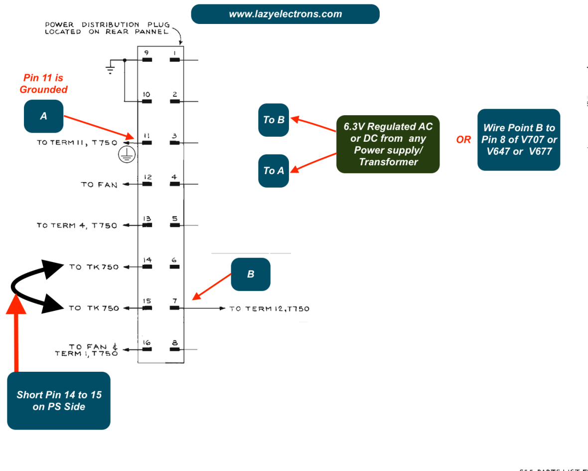
However, remember the power supply will not regulate as there is no load.So basic power up can be achieved and tested to ensure all rails are alive and regulates/follows the -150V rail.
Also the interesting part of heater regulator for the indicator unit. A 12-AS15 senses the 6.3 out of the heater transformer inside the indicator unit and uses it to control the current through the saturable reactor, which sits in series to the primary for the heater transformer inside the indicator unit.

The whole process, with schematic is explained in the video below :
Part2 – Power Supply Restore
Now to plug-ins. This unit came with a type H and type L vertical Plug-ins. Detailed restoration and explanation of the same down below here.
Part3 – Vertical Plug-in Restore
Next to H-Plug-ins. Both type 21 and 22. Here is the video explaining the Tek 500 series sweep circuit based on type 21 and overview of type 21/22 plug-ins with details of components.
Part4 – Sweep Horizontal Section/Plug-ins
Few details around the Horizontal Section of typical 500 series scopes. This is based on type 21 plug-in. High level map of the stages involved in sweep generation.

Here is the breakdown of the trigger section

And here is the breakdown of the sweep section

Here is the simplified signal flow through the sweep section.

Next : Restoring Indicator Unit.
Here is the map of the indicator unit top section

Here is the video of the first power up of the indicator unit and the Power supply unit.
Power supply test points in the Indicator unit.

Part5 – Indicator Unit – Restore
Note: At 28:00 of the video, please use the term “universal adapter” instead of “suicide cord” if you prefer so.
And here is the map of the vertical amplifier stages

And the next phase – Repair of the indicator unit coming Soon !
Part6 – Final Part – Indicator Unit Repair.
This video covers the repair of Time base 21 Plug-in and distributed vertifical amplifier for upper beam.
All the possible details are included in the video. However I will keep updating this blog as I find anything as missing.
Back to Home Page for more Restore/Repair Blogs

When Television started in New Zealand we had Tektronix ‘scopes too. The scope cart had a 230:230 isolation transformer 2 KVA as well as the power supply unit. They were certainly room heaters, but they worked. In another Youtube video you repaired a HP8116A generator. Are you able to share the circuit diagrams please? I have found the 156 pages of instruction and service, but there are no circuit diagrams included.
I enjoy your videos, please keep them coming.
Best regards,
Bernard
LikeLike
Thanks Bernard, You can find the manual with schematics here – http://citeseerx.ist.psu.edu/viewdoc/download?doi=10.1.1.357.8449&rep=rep1&type=pdf
LikeLiked by 1 person
Thank you for the file. I have just bought a 8116A that has been in a lab for 28 years. Not received yet but am told it is in very good condition. I can still check those capacitors that have a bad ESR. Well they are a good age! The cleaning of your 555 makes the appearance like new. I have just received a Tektronix 7633 with several plug-ins. A good wash makes all the difference. Have lots of fun with electronics – we do too. Regards Bernard
LikeLike
I also am a happy owner of a 555. Mine came from a well-maintained equipment pool of a large company, and is in good shape. Love your lab….mine has yet to find a real home, so it is drag out a few things and find a horizontal space.
I have yet to watch your videos, but am expecting to learn some good restoration tips.
Current restoration is a Tek AM503 current probe amp.
Thanks for sharing this!!
LikeLike
Thanks for the comment, congratulations and all the best!. 555 is very special.
LikeLike